
Manual
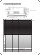


18
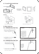
Figure 31 Switch ON /OFF Pump Figure 32 Switch ON/OFF all of the DC Loads
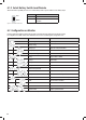
5.3.2 Switch Explanation
SWITCH FUNCTION DESCRIPTION
SILENT & Stop the fan ventilation in order to reduce the
noise Refer to 3.11
Press ‘Silent/Esc’ button until
shows on the screen, then press
‘Light/Enter’.
PUMP & To switch on/off pump
Pump on:
Pump off:
The detailed steps are shown as below Figure 31
LOAD & To switch off all the loads connected on DC
charger
The function is the same as Load switch in PM4SW10. The detailed steps
are shown as below Figure 32
/,*+7 To adjust the brightness and switch off the
EDFNOLJKWRIKHPRQLWRU
Total three levels of brightness
/,*+7)RU
Setting
7RVHWFORFNEDWWHU\EDWWHU\WDQNTXDQWLW\HWF +ROGGRZQWKH×/,*+7ØEXWWRQXQWLOWKH'DWH]RQH7DEOHVKRZV
the setting code. It means the unit enters the setting mode. For the full
details of setting codes, please refer to Chapter 6.2.1
PUMP PUMP LOAD LOAD
Load
Load
Load
OFF
OFF
ON
Load
ON
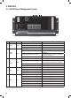
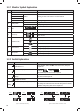
5.3.1 Monitor Symbol Explanation
No. DESCRIPTION COMMENTS
1 Water level 0%-25%-50%-75%-100%
:DWHU7DQN
EMPTY Flashing, the water is less than the recommended level:DWHU7DQN
:DWHU7DQN
:DWHU7DQN FULL Flashing, the gray water or waste water is more than the alarm level
2 :RUNLQJ0RGH
GRID AC grid status
&+$5*(21/< Battery charger only
3 Load
Status of DC-Load switch in system: on / off
BATTERY DC loads are powered by battery
4 Water Pump
Pump 1 is ON
Pump 1 is OFF
5 Alarm Error Code
Overload alarm
Over temperature alarm
System error code. Refer to the error codes on page 22
6 VCR connection
9ROWDJHFKDUJLQJUHOD\9&5LVFRQQHFWHG
9ROWDJHFKDUJLQJUHOD\9&5LVGLVFRQQHFWHG
7 Output power
Voltage of system output
Current of system output
Table 13 Monitor Symbol explanation
Load
ON
!
Table 14 Switch explanation