
Manual


9
2.3 Vehicle Battery Charger
$ORQJZLWKDSRZHUIXOFKDUJHUIRUVHUYLFHEDWWHU\30RIIHUVDöRDWFKDUJHRIXSWR$WRNHHSWKHVWDUWHUEDWWHU\FKDUJHGZKHWKHU
connected to the AC main or PV. When the starter battery is less than 12.4V, the PM400 starts charging after 30 minutes delay and stops
charging when voltage reaches 12.8V.
2.4 Power Supply Mode
,IQREDWWHU\LVDWWDFKHGWR30XQLWLWZLOOZRUNDVDSRZHUVXSSO\DXWRPDWLFDOO\ZLWKD9'&RXWSXW
2.5 MPPT Solar Charger Controller
PM400 has a built-in MPPT charger for the service battery with:
• Max input voltage 50VDC
• Max charging current 20A
• Max supply current 30A
2.6 Voltage Charging Relay (VCR or commonly known as a VSR)
30PDVWHUSRZHUXQLWKDVDEXLOWLQYROWDJHFKDUJLQJUHOD\9&5ZKLFKRIIHUVDFRQYHQLHQWVRXUFHWRFKDUJHWKHVHUYLFHEDWWHU\E\
alternator whilst engine is running. When the starter battery reaches 13.4VDC with threshold time delay, the VCR will charge the service
battery from the alternator. VCR will continue the charging until the starter battery voltage drops under 12.8VDC.
NOTE:7KH30ZKHQFKDUJLQJIURPWKHVWDUWHUEDWWHU\GRHVQRWSURYLGHWKHVWDJHFKDUJH,WVLPSO\WDNHVZKDWHYHUSRZHUDQG
charging is available from the vehicle alternator.
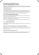
TYPE QTY DESCRIPTION POSSIBLE LOAD SUITABLE
Class A1 5 Relay controlled output with fuse, protected by
main master switch relay
:DWHUSXPS:DWHUWDQNKHDWLQJ79HWF
Class A2 3 PWM controlled, protected by master switch
relay
General lighting, such as, Ceiling light, Dining light,
Bedroom light etc.
Class B 3 Fused outputs, protected by master switch relay Ventilation fan etc.
Class C 2 Always alive load Fridge, security alarm etc.
Class D 1 Permanent on load Auto step
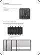
2.7 Categorised Outputs
The 14 outputs of PM400, are categorized into different groups for different controls.
Figure 9 Categorised output
7DEOH&DWHJRUL]HGRXWSXWVGHõQLWLRQ