USER'S MANUAL Hurricane 5004N Wireless-N (2T2R) 4-Port ADSL2+ Modem/Router Version 1.0 (Jan’10) 1.
PROLiNK® H5004N User Manual www.prolink2u.com TABLE OF CONTENTS Chapter 1 Introduction 1.1 Intended Audience 1.2 Definitions of Terms Used In This Document 1.3 Acronyms Used Throughout This Document 1.4 Usage Instructions 1.5 Questions or Comments on this Document 2 2 2 2 2 2 Chapter 2 System Overview 2.1 General Description 2.2 Specifications 3 3 3 Chapter 3 Hardware Installation 3.1 Hardware Requirements 3.2 LED Status Description 3.
PROLiNK® H5004N User Manual www.prolink2u.com Chapter 1 Introduction The Wireless-N (2T2R) 4-Port ADSL2+ Modem/Router user manual contains the guidance to install and configure PROLiNK Hurricane 5004N Wireless-N (2T2R) 4-Port ADSL2+ Modem/Router using the Web GUI. 1.1 Intended Audience This manual is intended for end users to access ADSL broadband service. 1.2 Definitions of Terms Used In This Document None. 1.3 Acronyms Used Throughout This Document None. 1.4 Usage Instructions None. 1.
PROLiNK® H5004N User Manual www.prolink2u.com Chapter 2 System Overview 2.1 General Description Hurricane 5004N wireless router is a high-speed Wireless-N (2T2R) 4-Port ADSL2+ Modem/Router that is specifically designed to connect to the Internet and to directly connect to your local area network (LAN) via high-speed 10/100 Mbps Ethernet, or wireless LAN (WLAN).
PROLiNK® H5004N User Manual - www.prolink2u.com 802.11b/g Data rates : 1, 2, 5.5, 6, 9, 11, 12, 18, 24, 36, 48, and 54Mbps, 802.
PROLiNK® H5004N User Manual - - 2.2.4 www.prolink2u.com Firewall o IP/Port filtering o MAC filtering ATM o ITU-T 1.610 F4/F5 OAM send and receiver loop-back o ATM QoS : CBR, rt-VBR, nrt-VBR and UBR o Multiple PVC : support 8 PVCs Management Version 1.
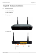
PROLiNK® H5004N User Manual www.prolink2u.com Chapter 3 Hardware Installation 3.1.1 10V Power Adapter 3.1.2 RJ-45 Ethernet cable 3.1.3 RJ-11 ADSL line Rear Panel Version 1.00 (Jan’10) 6 On/Off 3.2.2 Power Front Panel Reset 3.2.1 LAN LED Status Description Telephone Line 3.2 Hardware Requirements WPS 3.
PROLiNK® H5004N User Manual 3.3 www.prolink2u.com Hardware Setup Procedures 3.3.1 Connect RJ-11 line from Hurricane 5004N to the wall phone socket 3.3.2 Connect RJ-45 line from your PC LAN Port to Hurricane 5004N Ethernet port 3.3.3 Connect the 10V power adapter Version 1.
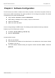
PROLiNK® H5004N User Manual www.prolink2u.com Chapter 4 Software Configuration The DSL device is an ADSL2+ wireless router. When you power on the device, the system will boot up and connect to ADSL automatically. The system provides a PVC for bridge test by default. The default configurations for the system are listed below. z LAN IP address: 192.168.1.1, Netmask: 255.255.255.0 z UART setting: 115200bps, 8 bits, no parity, 1 stop bit, no flow control.
PROLiNK® H5004N User Manual www.prolink2u.com Once you have connected to ADSL2+ router. You will see the status page. This page displays the ADSL modem/router’s current status and settings. This information is read-only except for the PPPoE/PPPoA channel for which user can connect/disconnect the channel on demand. Click the “Refresh” button to update the status Function buttons in this page: Connect / Disonnect The two buttons take effect only when PVC is configured as PPPoE/PPPoA mode.
PROLiNK® H5004N User Manual 4.1 www.prolink2u.com LAN Configuration This page shows the current setting of LAN interface. You can set IP address, subnet mask, and IGMP Snooping for LAN interface in this page. Fields in this page: Field Description IP Address The IP address your LAN hosts use to identify the device’s LAN port. Subnet Mask LAN subnet mask. IGMP Snooping Enable/disable the IGMP snooping function for the multiple bridged LAN ports.
PROLiNK® H5004N User Manual 4.2 www.prolink2u.com Wireless Configuration This section provides the wireless network settings for your WLAN interface. The wireless interface enables the wireless AP function for ADSL modem. 4.2.1 Basic Setting This page contains all of the wireless basic settings. Most users will be able to configure the wireless portion and get it working properly using the setting on this screen.
PROLiNK® H5004N User Manual www.prolink2u.com Function buttons in this page: Associated Clients Click it will show the clients currently associated with the ADSL modem. Apply Changes Change the settings. New parameters will take effect after save into flash memory and reboot the system. See section “Admin” for save details. Reset Discard your changes and reload all settings from flash memory. 4.2.2 Advanced Settings This page allows advanced users who have sufficient knowledge of wireless LAN.
PROLiNK® H5004N User Manual www.prolink2u.com Fields in this page: Field Description • • Authentication Type • Open System: Open System authentication is not required to be successful while a client may decline to authenticate with any particular other client. Shared Key: Shared Key is only available if the WEP option is implemented. Shared Key authentication supports authentication of clients as either a member of those who know a shared secret key or a member of those who do not. IEEE 802.
PROLiNK® H5004N User Manual www.prolink2u.com Function buttons in this page: Apply Changes Change the settings. New parameters will take effect after save into flash memory and reboot the system. See section “Admin” for save details. Reset Discard your changes and reload all settings from flash memory. 4.2.3 Security This screen allows you to setup the wireless security. Turn on WEP or WPA by using encryption keys could prevent any unauthorized access to your WLAN.
PROLiNK® H5004N User Manual www.prolink2u.com Use 802.1x Authentication Check it to enable 802.1x authentication. This option is selectable only when the “Encryption” is choose to either None or WEP. If the “Encryption” is WEP, you need to further select the WEP key length to be either WEP 64bits or WEP 128bits. WPA Authentication Mode There are 2 types of authentication mode for WPA. • WPA-RADIUS: WPA RADIUS uses an external RADIUS server to perform user authentication.
PROLiNK® H5004N User Manual 4.2.4 www.prolink2u.com Access Control This page allows administrator to have access control by enter MAC address of client stations. When Enable this function, MAC address can be added into access control list and only those clients whose wireless MAC address are in the access control list will be able to connect to your DSL device (or AP). Fields in this page: Field Wireless Access Mode MAC Address Version 1.
PROLiNK® H5004N User Manual www.prolink2u.com Function buttons for the setting block: Apply Changes Click to add this entry into the Current Access Control List. The Current Access Control List lists the client MAC addresses. Any wireless client with its MAC address listed in this access control list will be able to connect to the device. You can select the entries at the Select column and apply to the following function buttons.
PROLiNK® H5004N User Manual www.prolink2u.com Fields in this page: Field Description Disable WPS Check to disable the Wi-Fi protected Setup. WPS Status When AP’s settings are factory default (out of box), it is set to open security and un-configured state. “WPS Status” will display it as “UnConfigured”. If it already shows “Configured”, some registrars such as Vista WCN will not configure AP. Users will need to go to the “Backup/Restore” page and click “Reset” to reload factory default settings.
PROLiNK® H5004N User Manual www.prolink2u.com Start PBC Click to start the Push Button method of WPS. Apply Changes Click to commit changes. Reset It restores the original values. Start PIN Click to start the PIN method of WPS. 4.3 WAN Configuration There are three sub-menu for WAN configuration: [Channel Config], [ATM Settings], and [ADSL Settings]. 4.3.1 Channel Config ADSL modem/router comes with 8 ATM Permanent Virtual Channels (PVCs) at the most.
PROLiNK® H5004N User Manual www.prolink2u.com Function buttons in this page: Add Click Add to complete the channel setup and add this PVC channel into configuration. Modify Select an existing PVC channel by clicking the radio button at the Select column of the Current ATM VC Table before we can modify the PVC channel. After selecting an PVC channel, we can modify the channel configuration at this page. Click Modify to complete the channel modification and apply to the configuration.
PROLiNK® H5004N User Manual www.prolink2u.com Fields in this page: Field Description VPI Virtual Path Identifier. This is read-only field and is selected on the Select column in the Current ATM VC Table. VCI Virtual Channel Identifier. This is read-only field and is selected on the Select column in the Current ATM VC Table. The VCI, together with VPI, is used to identify the next destination of a cell as it passes through to the ATM switch.
PROLiNK® H5004N User Manual 4.3.3 www.prolink2u.com ADSL Settings The ADSL setting page allows you to select any combination of DSL training modes. Fields in this page: Field Description ADSL modulation Choose prefered xdsl standard protocols. • G.lite : G.992.2 Annex A • G.dmt : G.992.1 Annex A • T1.413 : T1.413 issue #2 • ADSL2 : G.992.3 Annex A • ADSL2+ : G.992.5 Annex A AnnexL Option Enable/Disable ADSL2/ADSL2+ Annex L capability. AnnexM Option Enable/Disable ADSL2/ADSL2+ Annex M capability.
PROLiNK® H5004N User Manual 4.4 www.prolink2u.com Services Configuration 4.4.1 DHCP Mode You can configure your network and DSL device to use the Dynamic Host Configuration Protocol (DHCP). This page provides DHCP instructions for implementing it on your network by selecting the role of DHCP protocol that this device wants to play. There are two different DHCP roles that this device can act as: DHCP Serve and DHCP Relay.
PROLiNK® H5004N User Manual www.prolink2u.com Function buttons in this page: Apply Changes Set new DHCP server configuration. New parameters will take effect after save into flash memory and reboot the system. See section “Admin” for save details. Undo Discard your changes. 4.4.3 DHCP Relay Configuration Some ISPs perform the DHCP server function for their customers’ home/small office network. In this case, you can configure this device to act as a DHCP relay agent.
PROLiNK® H5004N User Manual 4.4.4 www.prolink2u.com DNS Configuration There are two submenus for the DNS Configuration: [DNS Server] and [Dynamic DNS] 4.4.4.1 DNS Server This page is used to select the way to obtain the IP addresses of the DNS servers. Fields in this page: Field Description Attain DNS Automatically Select this item if you want to use the DNS servers obtained by the WAN interface via the auto-configuration mechanism.
PROLiNK® H5004N User Manual www.prolink2u.com 4.4.4.2 Dynamic DNS Each time your device connects to the Internet, your ISP assigns a different IP address to your device. In order for you or other users to access your device from the WAN-side, you need to manually track the IP that is currently used. The Dynamic DNS feature allows you to register your device with a DNS server and access your device each time using the same host name.
PROLiNK® H5004N User Manual www.prolink2u.com Function buttons in this page: Add Click Add to add this registration into the configuration. Remove Select an existing DDNS registration by clicking the radio button at the Select column of the Dynamic DNS Table. Click Remove button to remove the selected registration from the configuration. 4.4.5 Firewall Configuration Firewall contains several features that are used to deny or allow traffic from passing through the device. 4.4.5.
PROLiNK® H5004N User Manual www.prolink2u.com Function button for this first setting block: Apply Changes Click to save the setting of default actions to the configuration. Fields on the second setting block: Field Description Rule Action Deny or allow traffic when matching this rule. Direction Traffic forwarding direction. Protocol There are 3 options available: TCP, UDP and ICMP. Src IP Address The source IP address assigned to the traffic on which filtering is applied.
PROLiNK® H5004N User Manual www.prolink2u.com 4.4.5.2 MAC Filtering The MAC filtering feature allows you to define rules to allow or deny frames through the device based on source MAC address, destination MAC address, and traffic direction. Fields on the first setting block: Field Description Outgoing Default Action Specify the default action on the LAN to WAN bridging/forwarding path. Incoming Default Action Specify the default action on the WAN to LAN bridging/forwarding path.
PROLiNK® H5004N User Manual www.prolink2u.com Function buttons for this second setting block: Apply Changes Click to save the rule entry to the configuration. Function buttons for the Current Filter Table: Delete Selected Delete selected filtering rules from the filter table. You can click the checkbox at the Select column to select the filtering rule. Delete All Delete all filtering rules from the filter table. 4.4.5.
PROLiNK® H5004N User Manual www.prolink2u.com Fields in this page: Field Description Enable Port Forwarding Check this item to enable the port-forwarding feature. Protocol There are 3 options available: TCP, UDP and Both. Enable Check this item to enable this entry. Local IP Address IP address of your local server that will be accessed by Internet. Port The destination port number that is made open for this application on the LAN-side.
PROLiNK® H5004N User Manual www.prolink2u.com 4.4.5.4 DMZ A DMZ (Demilitarized Zone) allows a single computer on your LAN to expose ALL of its ports to the Internet. Enter the IP address of that computer as a DMZ (Demilitarized Zone) host with unrestricted Internet access. When doing this, the DMZ host is no longer behind the firewall. Fields in this page: Field Description Enable DMZ Check this item to enable the DMZ feature. DMZ Host IP Address IP address of the local host.
PROLiNK® H5004N User Manual www.prolink2u.com 4.4.5.5 URL Blocking The URL Blocking is the web filtering solution. The firewall includes the ability to block access to specific web URLs based on string matches. This can allow large numbers of URLs to be blocked by specifying only a FQDN (such as tw.yahoo.com). The URL Blocking enforce a Web usage policy to control content downloaded from, and uploaded to, the Web.
PROLiNK® H5004N User Manual www.prolink2u.com Add FQDN Add FQDN into URL Blocking table. Delete Selected FQDN Delete the selected FQDN from the URL Blocking table. You can click the checkbox at the Select column to select the Blocked FQDN. Add Filtered Keyword Add filtered keyword into Keyword Filtering table. Delete Selected Keyword Delete the selected keyword from the keyword Filtering table. You can click the checkbox at the Select column to select the filtered keyword. 4.4.5.
PROLiNK® H5004N User Manual www.prolink2u.com Fields in this page: Field Description Domain Blocking capability Check this item to enable the Domain Blocking feature. Domain The blocked domain. If the URL of Taiwan Yahoo web site is tw.yahoo.com, the domain can be yahoo.com. Function buttons in this page: Apply Changes Click to disable/enable the Domain Block capability Add Domain Add domain into Domain Block table. Delete Selected Domain Delete the selected domain from the Domain Block table.
PROLiNK® H5004N User Manual www.prolink2u.com The IGMP Proxy page allows you to enable multicast on WAN and LAN interfaces. The LAN interface is always served as downstream IGMP proxy, and you can configure one of the available WAN interfaces as the upstream IGMP proxy. Upstream: The interfaces that IGMP requests from hosts are sent to the multicast router. Downstream: The interface data from the multicast router are sent to hosts in the multicast group database.
PROLiNK® H5004N User Manual 4.4.7 www.prolink2u.com UPnP Configuration The DSL device supports a control point for Universal Plug and Play (UPnP) version 1.0, and supports two key features: NAT Traversal and Device Identification. This feature requires one active WAN interface. In addition, the host should support this feature. In the presence of multiple WAN interfaces, select an interface on which the incoming traffic is present.
PROLiNK® H5004N User Manual 4.4.8 www.prolink2u.com RIP Configuration RIP is an Internet protocol you can set up to share routing table information with other routing devices on your LAN, at your ISP’s location, or on remote networks connected to your network via the ADSL line. Most small home or office networks do not need to use RIP; they have only one router, such as the ADSL Router, and one path to an ISP.
PROLiNK® H5004N User Manual www.prolink2u.com Fields on the first setting block: Field Description RIP Enable/disable RIP feature. Function buttons for the second setting block in this page: Apply Changes Click to save the setting of this setting block to the system configuration Fields on the second setting block: Field Description Interface The name of the interface on which you want to enable RIP.
PROLiNK® H5004N User Manual www.prolink2u.com Fields in this page: Field Description Ageing Time Set the Ethernet address ageing time, in seconds. After [Ageing Time] seconds of not having seen a frame coming from a certain address, the bridge will time out (delete) that address from Forwarding DataBase (fdb). 802.1d Spanning Tree Enable/disable the spanning tree protocol Function buttons in this page: Apply Changes Save this bridge configuration.
PROLiNK® H5004N User Manual www.prolink2u.com : Fields in this page: Field Description Enable Check to enable the selected route or route to be added. Destination The network IP address of the subnet. The destination can be specified as the IP address of a subnet or a specific host in the subnet. It can also be specified as all zeros to indicate that this route should be used for all destinations for which no other route is defined (this is the route that creates the default gateway).
PROLiNK® H5004N User Manual www.prolink2u.com Update Update the selected destination route on the Static Route Table. Delete Selected Delete a selected destination route on the Static Route Table. Show Routes Click this button to view the DSL device’s routing table. The IP Route Table displays, as shown in Figure. Version 1.
PROLiNK® H5004N User Manual 4.5.3 www.prolink2u.com SNMP Configuration Simple Network Management Protocol (SNMP) is a troubleshooting and management protocol that uses the UDP protocol on port 161 to communicate between clients and servers. The DSL device can be managed locally or remotely by SNMP protocol. Fields in this page: Field Description System Description System description of the DSL device. System Contact Contact person and/or contact information for the DSL device.
PROLiNK® H5004N User Manual 4.5.4 www.prolink2u.com Port Mapping The DSL device provides multiple interface groups. Up to five interface groups are supported including one default group. The LAN and WAN interfaces could be included. Traffic coming from one interface of a group can only be flowed to the interfaces in the same interface group. Thus, the DSL device can isolate traffic from group to group for some application.
PROLiNK® H5004N User Manual www.prolink2u.com Function buttons in this page: Apply Changes Save configuration to system. New configuration will take effect after saving into flash memory and rebooting the system. See section “Admin” for details. 4.5.5 IP QoS The DSL device provides a control mechanism that can provide different priority to different users or data flows. The QoS is enforced by the QoS rules in the QoS table. A QoS rule contains two configuration blocks: Traffic Classification and Action.
PROLiNK® H5004N User Manual www.prolink2u.com Fields on the first setting block of this page: Field Description IP QoS Enable/disable the IP QoS function. Source IP The IP address of the traffic source. Source Netmask The source IP Netmask. This field is required if the source IP has been entered. Destination IP The IP address of the traffic destination. Destination Netmask The destination IP Netmask. This field is required if the destination IP has been entered.
PROLiNK® H5004N User Manual 4.5.6 www.prolink2u.com Remote Access (Moved to ACL Config – please refer to page 57) The Remote Access function can secure remote host access to your DSL device from LAN and WLAN interfaces for some services provided by the DSL device.
PROLiNK® H5004N User Manual 4.6 www.prolink2u.com Diagnostic The DSL device supports some useful diagnostic tools. 4.6.1 Diagnostic Test The Diagnostic Test page shows the test results for the connectivity of the physical layer and protocol layer for both LAN and WAN sides. Fields in this page: Field Description Select the Internet Connection The available WAN side interfaces are listed. You have to select one for the WAN side diagnostic. Version 1.
PROLiNK® H5004N User Manual 4.7 www.prolink2u.com Admin 4.7.1 Save & Reboot Function buttons in this page: 1. Save Current Configuration >> Apply 2. Factory Default Configuration >> Apply 3. Reboot >> restart the modem 4.7.2 Backup/Restore This page allows you to backup and restore your configuration into and from file in your host. Version 1.
PROLiNK® H5004N User Manual 4.7.3 www.prolink2u.com System Log This page shows the system log. 4.7.4 Password The first time you log into the system, you use the default password. There are two-level logins: admin and user. The admin and user password configuration allows you to change the password for administrator and user. Fields in this page: Field Description User Name Selection of user levels are: admin and user. Old Password Enter the old password for this selected login.
PROLiNK® H5004N User Manual 4.7.5 www.prolink2u.com Upgrade Firmware To upgrade the firmware for the DSL device: • Click the Browse button to select the firmware file. • Confirm your selection. • Click the Upload button to start upgrading. IMPORTANT! Do not turn off your DSL device or press the Reset button while this procedure is in progress. 4.7.6 ACL The Access Control List (ACL) is a list of permissions attached to the DSL device. The list specifies who is allowed to access this device.
PROLiNK® H5004N User Manual www.prolink2u.com 2. WAN – you can enable web(http)/telenet/ftp/tftp/snmp/ping for WAN access 4.7.7 Time Zone Simple Network Timing Protocol (SNTP) is a protocol used to synchronize the system time to the public SNTP servers. The DSL device supports SNTP client functionality in compliance with IETF RFC2030.
PROLiNK® H5004N User Manual www.prolink2u.com Fields in this page: 4.7.8 Field Description Current Time The current time of the specified time zone. You can set the current time by yourself or configured by SNTP. Time Zone Select The time zone in which the DSL device resides. Enable SNTP client update Enable the SNTP client to update the system clock. SNTP server The IP address or the host name of the SNTP server. You can select from the list or set it manually.
PROLiNK® H5004N User Manual www.prolink2u.com Fields in this page: ACS Field Description URL ACS URL. For example, http://10.0.0.1:80 https://10.0.0.1:443 User Name The username the DSL device should use when connecting to the ACS. Password The password the DSL device should use when connecting to the ACS.
PROLiNK® H5004N User Manual 4.8 www.prolink2u.com Statistics The DSL device shows the different layer of network statistics information. 4.8.1 Interfaces You can view statistics on the processing of IP packets on the networking interfaces. You will not typically need to view this data, but you may find it helpful when working with your ISP to diagnose network and Internet data transmission problems. To display updated statistics showing any new data since you opened this page, click Refresh.
PROLiNK® H5004N User Manual 4.8.2 www.prolink2u.com ADSL This page shows the ADSL line statistic information. Version 1.
PROLiNK® H5004N User Manual www.prolink2u.com Chapter 5 Channel Mode Configuration ADSL router supports multiple channel operation modes. This section will show procedures to configure the router. 5.1 Bridge Mode ADSL modem/router can be set to Bridge mode. 1. Open the WEB page at “WAN interface/Channel Configuration”. 2. Select your VPI/VCI under ATM VC table 3. Change the Channel Mode to “1483 Bridged”. Set the parameters VPI/VCI and Encapsulation mode according to the CO DSLAM’s setting. 4.
PROLiNK® H5004N User Manual 5.2 www.prolink2u.com MER (Mac Encapsulating Routing) Mode 1. Open the WEB page at “WAN interface/Channel Configuration”. 2. Select the Channel Mode to “1483 MER”. Set the parameters VPI/VCI and Encapsulation mode according to the CO DSLAM’s setting. 3. Set “Local IP Address:” according to the IP that ISP assign for your router. Set “Remote IP Address” to the ISP’s gateway. 4. Click “Add” button to add this channel into VC table. 5.
PROLiNK® H5004N User Manual 5.3 www.prolink2u.com PPPoE Mode 1. Open the WEB page at “WAN interface/Channel Configuration”. 2. Select the Channel Mode to “PPPoE”. Set the parameters VPI/VCI and Encapsulation mode according to the CO DSLAM’s setting. 3. Enter user/password from your ISP. 4. Click “Add” button to add this channel. 5. Enable DHCP server to allow the local PCs share the PPP connection. Reference to section 4.6.1 DHCP Server Configuration. 6. Set DNS address from your ISP.
PROLiNK® H5004N User Manual 5.4 www.prolink2u.com PPPoA Mode 1. Open the WEB page at “WAN interface/Channel Configuration”. 2. Select the Channel Mode to “PPPoA”. Set the parameters VPI/VCI and Encapsulation mode according to the CO DSLAM’s setting. 3. Enter user/password from your ISP. 4. Click “Add” button to add this channel. 5. Enable DHCP server to allow the local PCs share the PPP connection. Reference to section 4.6.1 DHCP Server Configuration. 6. Set DNS address from your ISP.
PROLiNK® H5004N User Manual 5.5 www.prolink2u.com 1483 Routed Mode 1. Open the WEB page at “WAN interface/Channel Configuration”. 2. Select the Channel Mode to “1483 Routed”. Set the parameters VPI/VCI and Encapsulation mode according to the CO DSLAM’s setting. 3. In WAN IP settings, give the local and remote IP address from your ISP or use DHCP to get them automatically if your ISP support it. Local IP is the address of ADSL router. Remote IP is the ISP’s gateway address. 4.
PROLiNK® H5004N User Manual www.prolink2u.com Chapter 6 Protocol Stacks 6.1 1483 Bridged Model IP Eth ernet IP Et hernet Ethernet Et he rn et LLC /SNAP (14 83 -B) LLC/ SNAP (148 3-B ) AAL5 AAL5 SAR SAR ATM 100 BaseT 100Ba seT PC x DSL xDSL ATU-R ATM ATM SONET/ SDH SONET/ SDH DSLAM BRAS 1483 Bridged Channel Mode Scenario 6.
PROLiNK® H5004N User Manual 6.3 www.prolink2u.com PPPoE Model IP Eth erne t IP Et he rn et IP IP PPP PPP PPPoE PPPoE Eth erne t Eth erne t L LC/SNAP (14 83 -B) LLC /SNAP (14 83 -B) AAL5 AAL5 SAR SAR ATM 1 00 BaseT PC 1 0 0B aseT x DSL x DSL ATU-R ATM ATM SONET/ SDH SONE T/SDH DSLAM BRAS PPPoE Channel Mode Scenario 6.
PROLiNK® H5004N User Manual 6.5 www.prolink2u.com 1483 Routed Model IP IP Eth erne t Et he rn et IP IP L LC/SNAP (14 83 -R) LLC /SNAP (14 83 -R) AAL5 AAL5 SAR SAR ATM 1 00 BaseT PC 1 0 0B aseT x DSL x DSL ATU-R ATM ATM SONET/ SDH SONE T/SDH DSLAM 1483 Routed Channel Mode Scenerio Version 1.
PROLiNK® H5004N User Manual www.prolink2u.com Chapter 7 Questions & Answers Q1 Why all LED indicators are off? A1 • Check the connection between the power adaptor and the power socket. • Check the power switch is on or not. Q2 Why LAN LED is not lighting? A2 • Check the connection between the ADSL modem and your computer, hub, or switch. • Check the running status of your PC, hub, or switch, and ensure that they are working normally.
PROLiNK® H5004N User Manual www.prolink2u.com Chapter 8 Technical Support REGISTER ONLINE FOR FREE WARRANTY. FREE TECHNICAL SUPPORT HOTLINE: Monday to Friday, 9.00 am – 6.00 pm (Closed on Saturdays, Sundays and Public Holidays) • SINGAPORE : (65) 6357 0666 • MALAYSIA : (60) 3 8023 9151 • INDONESIA : (62) 21 3483 1777 WALK-IN SUPPORT: Monday to Friday, 9.00 am – 6.
Register Online For Your Product Warranty www.prolink2u.com SINGAPORE FIDA INTERNATIONAL (S) PTE LTD Block 16 Kallang Place, #06-02 Kallang Basin Industrial Estate, Singapore 339156. Tel : (65) 6357 0668 Email : support@fida.com MALAYSIA FIDA SYSTEMS (M) SDN BHD 29 Jalan USJ 1/31, 47600 Subang Jaya, Selangor Darul Ehsan, Malaysia. Tel : (60) 3 8024 9151 Email : support_my@fida.com INDONESIA PROLiNK INDONESIA Jl. Cideng Barat No. 79 Jakarta Pusat 10150 Indonesia.