
User Manual


5. Prepare each battery in advance by cleaning each terminal post with a wire brush until a
shiny surface is obtained.
6. Run cables free from sharp objects and hold each in place with cable ties. Coil excess
cable, do not cut or shorten the length of the cables, as in-line fuses are located 4 inches
from the end of each red (positive) cable. In addition, there are fuses in all but one of the black
(negative) leads. These fuses protect the charger and output cables in the event of a wiring
short. We recommend the use of wire ties or cable clamps to provide strain relief for the cables
and to reduce the risk of damage to the cables or connections.
7. Connect the DC output cables as illustrated on pages 11-18. Make sure the (black) wires
are connected as illustrated to the negative side of the battery and the (red) wires are connected
to the positive side of the battery.
Important Note: Your ProSport charger will not operate properly if it is not connected properly
to each battery. Reminder, The ProSport and each DC jacketed bank cable must be properly
connected to "individual 12V batteries". Number of DC jacketed bank cables equals the number
of batteries that must be individually connected. Example: a 3 bank ProSport 20 Three Bank
charger must be connected to 3 individual 12V batteries, as illustrated on pages 11-18. Simply
choose the illustration that has the same number of charger output bank cables as your ProSport
Battery Charger in hand and wire exactly as shown (choose the illustration that matches your
application) for proper charger operation.
8. Make sure all DC connections are correct, tight, and free from corrosion.
9. Locate the AC power cord in an open-air area of your boat at least 21 inches from the
charger, batteries, and fuel fill lines.
10. Connect a heavy duty UL approved extension cord to the ProSport charger first. After
connecting the extension cord to the charger, proceed to plug the extension cord to a nearby
120 VAC GFCI protected (Ground Fault Circuit Interrupt) outlet. Always remove the extension
cord from the 120VAC outlet first when charging is completed, followed by unplugging the
charger. You are now connected and charging your batteries. View the LED indicators.
4 Steps to Wire your ProSport Charger Correctly
STEP 1: Simply choose the illustration that has the same number of charger output bank
cables as your ProSport Battery Charger in hand and wire exactly as shown (choose the
illustration that matches your application) for proper charger operation.
STEP 2: Do not remove your batteries series or parallel jumper cables that interconnect
batteries to each other. ProSport Chargers are designed with isolated outputs and series
or parallel jumper cables do not have to be removed.
STEP 3: Your ProSport charger will not operate properly if it is not connected properly
to each battery. Reminder, the ProSport and each DC jacketed bank cable must be
properly connected to "individual 12V batteries". Number of DC jacketed bank cables
equals the number of batteries that must be individually connected. Example: a three
bank ProSport 20 3 Bank must be connected to 3 individual 12V batteries. As Illustrated
on Pages 11-18. Select your battery / trolling motor configuration for the specific wiring
illustration need for your charger.
10
Installation
INSTALLATION
11
STEP 4: Incorrect wiring will result in reverse polarity or high reverse voltage, in the event this
happens, the ProSport Charger has been designed to not fail as a result, however it will cause
the charger to "internally disconnect" and provide "no output" until the (reverse polarity caused
by putting the "red" + lead on a - negative battery terminal) and or the (high reverse DC voltage
caused by taking one bank cable and spreading it across two batteries) is corrected, using the
wiring diagrams as shown on pages 11-18. In the event of a reverse polarity connection or an
improper battery connection or if an output is not connected to a battery the appropriate red
battery bank trouble LED will illuminate identifying the battery and wiring connections where a
fault is present. See page 21 for further details.
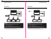
Installation
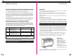
When connecting each jacketed battery charger cable, make sure it is connected
to only one 12 VDC battery
and observe the polarity and color of all connections:
Red Wire = + (Positive) Battery connection
Black Wire =
-
(Negative) Battery connection
The black wire can never be connected to a terminal with red wires. Only black.
Important: The pair of red and black wires in 1 cable jacket MUST GO TO THE SAME 12VDC battery.
Each charger cable
must
be connected to 1 battery,
just as shown. Observe black
to (-) and red to (+). Do this
for each battery.
T
o
p
V
i
e
w
o
f
B
a
t
t
e
r
y
cable jacket
Group size 24
thru 31 only
red (+)
black (-)
+
_
Installation
When connecting to an engine start battery only connect the battery bank cable that is LABELED:
"FOR ENGINE BATTERY USE THIS BANK CABLE ONLY".
If your application is for 4D or 8D large capacity batteries, please refer to ProMariner's website
www.promariner.com and view our ProNauticP Hardwired Charger Assortment for a model that is
correct for this group size of batteries.
Application Tip
WIRING DIAGRAMS