
Manual

7
Installation Guidelines
Installation Continued
7. Run your cables free from sharp objects and hold each of them in place with
cable ties. Coil excess cable, do not cut or shorten the length of the cables as there
are in-line fuses located 4 inches from the end of each red (positive) cable. These
fuses are in place to protect the charger and output cables in the event of a short
or reverse polarity.
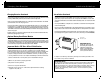
8. Connect the DC output cables as illustrated on page 8. Make sure the (black or
yellow) wires are connected as illustrated to the negative side of the battery and
the red wires are connected to the positive side of the battery.
9. Make sure all DC connections are tight and correct.
10. Locate the AC power cord in an open-air area of your boat at least 21 inches
from the charger, batteries and fuel fill lines.
11. Connect a heavy duty U.L. approved extension cord to the ProMite charger first.
After connecting the extension cord to the charger then proceed to plug the
extension cord to a nearby 120VAC GFCI protected (Ground Fault Circuit Interrupt)
outlet. Always remove the extension cord from the 120VAC outlet first when charging
is completed, followed by unplugging the charger.
You are now connected and charging your batteries. View the LED indicators.
Assuming your batteries are discharged you should observe both the green "Power"
LED and the red "Charging" LED on, indicating charging mode is in process.
Lead Acid (Flooded) / Gel Charging Profile
The ProMite On-Board Marine Battery Charger is factory set with a safe
charging profile for lead acid (flooded) and gel batteries.
8
Installation Guidelines / Charging Your Batteries
IMPORTANT NOTICE
If only two batteries are used with a 3 bank charger, than connect the unused
output cable to either one of the two batteries, as instructed in item 8 above
Always connect each charger output to a single 12V battery even if the batteries
are wired series for 24V or 24Vwith an engine battery.
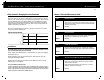
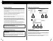
ProMite Series Wiring Diagrams
ProMite Series Wiring Diagrams
Engine Only
Battery 3
Trolling Motor
Battery 2
Trolling Motor
Battery 1
+
_
+
_
+
_
AC power
output no.1
output no.2
output no.3
ProMite5|5|3
Wiring Diagram
red
red
red
black or
yellow
black or
yellow
black or
yellow
Engine or Trolling
Motor Battery 2
Trolling Motor
Battery 1
+
_
+
_
AC power
output no.1
output no.2
ProMite5|5 Wiring Diagram
red
black or
yellow
red
black or
yellow
Engine or Trolling
Motor Battery 1
+
_
AC power
output no.1
ProMite5 Wiring Diagram
red
black or
yellow
Charging Batteries
The ProMite Series is designed to charge and maintain your batteries. Please follow these
steps each time you use your ProMite Charger:
1. Open all battery compartments and ventilate for at least 15 minutes before applying AC
power to your charger. While charging your batteries make sure to keep your battery
compartment open allowing for free air ventilation.
2. Make sure all DC battery connections are tight and clean. Follow battery manufacturer's
recommendations for battery cell caps. (loosen caps if applicable)