Bear Operation and Installation Guide 20, 30, 40, 50 KLZ Stationary cast iron boiler Output range 17 – 44.5 kW Continuous output modulation Integrated 110 l hot water tank www.protherm.eu Protherm spol. s r.o. Pplk. Pľjušťa 45 909 01 Skalica, Slovakia Tel.: +421 34 6966 101 Fax: +421 34 6966 111 Your service organisation: EN version xxxx_01 - v.
Bear 20 (30, 40, 50) KLZ The boiler’s Serial no. is shown on the plate which is attached to the rear side of the control panel. The control panel is accessible after removing the front cover. In the section “Operating Instructions” you will find description of the boiler’s main functions and guidelines on how to handle the boiler safely. The section “Installation Instructions” is for skilled workers only. Obsah Table of contents Introduction ...........................................
Introduction 1. The boiler and all the associated equipment must be installed and used in accordance with the installation design, all the corresponding valid legal prescriptions and technical norms and with the manufacturer’s instructions. 2. The boiler may be installed only in an environment for which it is designed. 3. After installation, the boiler may be put into operation by an authorised service organisation only. 4. The boiler complies with the prescriptions valid in the Slovak Republic.
the Operation guide, Service Book etc.). If the boiler is not put into operation, the original packaging of the boiler must be available for the potential further transport thereof.
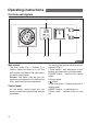
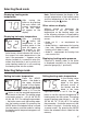
Operating instructions Controls and signals 3 6 7 1 2 4 5 Fig. 1 Main switch The main switch (Fig. 1, Position 7) is used to switch the boiler on or off. The main switch is situated on the right side of the boiler control panel. Caution: The boiler must be put into operation and switched on for the first time by an authorised service organisation! Control panel On the boiler’s control panel you can monitor current values and set the required parameters.
Selecting Read mode Displaying heating water temperature After turning the boiler on by pressing the main switch, the current temperature of the hot water will appear on the display. Displaying hot water temperature After pressing the button, the temperature of the heating water in the tank will appear on the display. In this display the diode is lit in the upper lefthand corner, which indicates the value of the current hot water temperature in the tank.
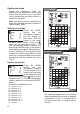
Equithermal mode Curve slope Setting the equithermal mode, i.e. selection of the equithermal curve slope and parallel shift of the curve, is possible only in the case that an outdoor sensor is attached to the boiler. Note: If no outdoor sensor is attached, the boiler will not enable the user to transfer to setting mode E and P. Setting curve slope Press the MODE button until the parameter E appears on the display. At the same time the diode in the upper left-hand corner flashes.
Schematic diagram of boiler control Valid only for connection of outdoor sensor Fig.
Timer switch The timer switch serves for setting attenuation of heating the hot water in the tank, i.e. during the interval of the set attenuation the boiler does not heat the water in the hot water tank to maintain temperature. The length of the attenuation interval is set by the cogs on the perimeter of the clock rotor. The interval is set to where the cogs face outwards – see diagram. There may be more than one interval, i.e. there may be a number of attenuations per day.
Starting up and shutting down boiler Starting up the boiler Important: Putting the boiler into operation and starting it up for the first time must be performed by an authorised service only! If you wish to start the boiler up after it has been put into operation, make sure that: 1 the boiler is connected to the electrical power supply; 2 all stop valves (heating water, hot water, gas) underneath the boiler are opened; 3 the heating water pressure is lower than indicated on the pressure gauge – red adjustab
Operation of boiler with equithermal control The boiler regulates the heating water temperature on the basis of outdoor temperature changes. In the case of this type of regulation it is necessary to set the equithermal curve according to the required heating water temperature. It is also necessary to attach an outdoor temperature sensor. The procedure for setting equithermal curves is outlined on page 6 of this manual.
than 85°C. The boiler is switched off when the temperature of the heating water is higher than 90°C (fault F3). Running pump depending on heating water temperature The boiler enables setting running of the pump after a certain selected temperature has been reached. This function can be set only by an authorised service technician. Chimney draught control system The boiler is equipped with a “Chimney draught control system” (CDCS). Upon an accumulation of combustion gases in the boiler, i.e.
Professional maintenance of boiler Once per year, preferably before the beginning of the heating season, we recommend that the boiler is checked and set by a service organisation. This check is not covered by the boiler’s warranty. The specific tasks to be performed are specified in the Service Book.
Technical specifications 20 (30) KLZ Bear 20 KLZ Category . . . . . . . . . . . . . . . . . . . . . . . . . . . . . . . . . . . . . . . . . . . . . . . II2H3P Bear 30 KLZ Version . . . . . . . . . . . . . . . . . . . . . . . . . . . . . . . . . . . . . . . . . . . . B11BS Ignition . . . . . . . . . . . . . . . . . . . . . . . . . . . . . . . . . . . . . . . . . . . . . .electronic Fuel . . . . . . . . . . . . . . . . . . . . . . . . . . . . . . . . . . . . . . .G20 / G31 . . . . . . . . . . . .
Technical specifications 40 (50) KLZ Bear 40 KLZ Category . . . . . . . . . . . . . . . . . . . . . . . . . . . . . . . . . . . . . . . . . . . . . . . II2H3P Bear 50 KLZ Version . . . . . . . . . . . . . . . . . . . . . . . . . . . . . . . . . . . . . . . . . . . . B11BS Ignition . . . . . . . . . . . . . . . . . . . . . . . . . . . . . . . . . . . . . . . . . . . . . .electronic Fuel . . . . . . . . . . . . . . . . . . . . . . . . . . . . . . . . . . . . . . .G20 / G31 . . . . . . . . . . . .
Connection dimensions of boiler 20 (30, 40, 50)KLZ 730 e ød 505 177,5 130 30 KLZ 285 106 505 220 130 40 KLZ 242,5 21 505 262,5 150 50 KLZ 285 21 590 305 180 792 c 191 607 b 327,5 460 a 20 KLZ 120 290 TYPE 976 153 869 892 c e 50 1385 a A – hot water input 3/4” C – hot water output 3/4” E – heating water output 1” B – hot water circulation 3/4” D – heating water input 1” F – gas input 3/4” Fig.
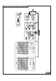
Schematic diagram of boiler 1. Control panel 10. Backflow valve for HeW circuit 19. Hot water (cold water) inlet 2. “POLO-TURBO” superstructure 11. Backflow valve for HoW circuit 20. Filling and discharge 3. Combustion gas collector 12. Gas inlet 21. Burner plate 4. Automatic bleeding valve 13. Heating water outlet 22. Gas valve with ignition automatic 5. Safety valve 14. Boiler body 23. Hinged frontal cover 6. Pump for HoW heating circuit 15. Heating water inlet 24.
Installation instructions Introduction The PROTHERM Bear 20 (30, 40, 50) KLZ boiler is compatible with common types of hot water heating systems and heating radiators. Important: The PROTHERM boilers must be put into operation only by authorised organisations according to Czech Bureau of Occupational Safety and Czech Safety Inspectorate Notice No. 21/1979 (in the wording of Public Notice No. 554/1990 Coll.).
The boiler is designed for combustion gases to be discharged (via a chimney inlet) with a minimum stabilised thrust of 2 Pa. The boiler is connected to the chimney inlet by a flue – for the boilers PROTHERM 20, 30 KLZ with Ø 130 mm, for the type PROTHERM 40 KLZ with Ø 150 mm and for the type PROTHERM 50 KLZ with Ø 180 mm. Important: It is prohibited to place any objects restricting the combustion gas flow inside the flue (e.g. various types of heat exchangers to utilise their residual heat).
stress on all its elements during operation. In cases where the total quantity of heating water in the closed system exceeds 180 l it is essential to include a second expansion vessel in the system. This vessel must have an identical same construction, i.e. it must be closed, with a membrane. The resultant value of the water pressure in the system when cold is constantly indicated by the red (adjustable) hand of the boiler pressure gauge.
Delivery completeness Content of boiler delivery Content of delivery PROTHERM Bear 20 (30, 40, 50) KLZ boilers are supplied completely assembled and functionally tested. Associated armatures (safety valve and backflow clack valve) are enclosed with the boiler for equipment for the hot water inlet, as well as a set of adjustable legs. The delivery includes (Fig. 8): 1. The boiler 2. Operation and Installation Guide 3. Service Book 4. List of service centres 5.
Preparing for boiler installation Boiler equipment The boiler PROTHERM 20 (30, 40, 50) KLZ comprises the following parts: - cast iron boiler body with thermal insulation. - burner plate including gas path and starting equipment, - combustion gas catcher with thrust breaker, - hydraulic construction, - boiler casing with control panel, - hot water tank.
Casing This is composed of covers, firmly attached to the back wall and side plates, a detachable frontal wall and detachable upper part. The upper part contains a horizontal control panel, and a vertical control panel beneath the upper edge of the detachable frontal wall. Hot water tank This is a cylindrical vessel containing spiral piping. The heating water passes through the piping and heats the utility water in the vessel.
Installing the boiler In the case of service interventions into the boiler it is unconditionally necessary whenever the boiler is collected to the electrical power source (even when the mains switch of the boiler is off) to abide by the safety prescriptions for operation and work on electrical equipment (provision of norm STN 34 3100). The boiler casing can be disassembled. The frontal section is secured by spring clamps in the upper corners of the casing.
damage, and must be replaced with new ones before the end of their useful life or before their reliability to meet their nominal parameters (as stated by their manufacturers) is diminished. Properties of heating system and filling the heating system It is necessary to set the temperature of the emergency thermostat according to the type of implementation of the heating system (open or closed). For open systems the emergency temperature is set to 95°C, for closed systems 105°C.
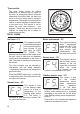
Operating the boiler Preparing and starting the boiler Check the water pressure on the boiler pressure gauge. By opening the gas cock gas is inlet into the boiler. Connect the plug of the flexible power cord into the socket and press the mains button. The heating and hot water are set to approx. ½ of their volume. In the first additional “mode” we select automatic setting of the heating water temperature for running of the pump, for subsequent actual operation this is adjusted further as applicable.
Before commencing setting, when the boiler is switched off (plug of electrical power cord is removed from socket), it is necessary to: - detach the covering (metal) plug (A) - relax the closing screw of the measurement point (2) of outflow gas pressure and slide on the tube of the Umanometer (screw not removed) Maximum output - The boiler is put into operation and left to work during hot water consumption at maximum output. The course of measurement should not be interrupted by switching off the boiler e.
Service (additional) modes Setting attenuation in heating The parameter “u” appears on the display and the diode flashes in the upper left-hand corner. This parameter is used to set the attenuation in the heating system, which depends on the timer switch. In this setting the attenuation interval is identical to the attenuation interval for heating the hot water tank up to the required temperature, i.e. during this interval the set heating water value drops by the value of this parameter.
Electrical connection of boiler The boiler is connected to power supply by a three-core flexible cord with a plug. A fixed socket through which the boiler is connected to power mains must comply with the provisions of STN 33 2000-4-46. This must always have a protective (earth) contact (pin), reliably connected by a PE or PEN wire (yellow-and-green).
Diagram of connection of external elements Terminals for connecting outdoor sensor 1 2 Room control unit 3 4 5 6 BOILER Power cable (without plug) Select this connection only if you want to connect a room control unit Connection of external control unit (not part of delivery) Main power connection (230V) Fig. 10 Converting to different fuel If it is necessary to convert to a different type of fuel (natural gas to propane and vice versa), the boiler is reconstructed in the following manner.
– otherwise this could cause damage (tearing) of “SOFT-LITE”). The red rotating knob underneath the plug has an arrow, which: - if turned in the direction of gas flow is at the value MAX; - if turned against the direction of gas flow is at the value MIN. 7.
31 Ionising electrode Ignition electrode Automatic ignition S4565 AM chimney 10V-IP 44 Gas valve Honeywell red grey blue Heating circuit pump black Yellow/ green black blue Yellow/ green Yellow/ green black blue black blue blue Main switch blue Tank pump Reset button Emergency thermostat Combustion gas thermostat Yellow/ green Chimney valve (turbo superstructure) black brown Power cable Electrical diagram of boiler PROTHERM 20 (30, 40, 50) KLZ grey Timer switch for setting at