Copyright © 1998 Proxim, Inc., Mountain View, CA. All rights reserved. This manual and the software described in it are copyrighted with all rights reserved. No part of this publication may be reproduced, transmitted, transcribed, stored in a retrieval system or translated into any language in any form by any means without the written permission of Proxim, Incorporated. Trademarks RangeLAN, the RangeLAN logo, RangeLAN2, and Proxim are trademarks of Proxim, Inc.
Warranty Return Policy If you have a problem with your RangeLAN2 product, please call Proxim Technical Support at 650-526-3640. Proxim Technical Support will assist with resolving any technical difficulties you may have with your Proxim product. If your product is found to be defective, you may return the product to Proxim after obtaining an RMA (Return Materials Authorization) number from Proxim Technical Support. The product must be returned in its original packaging.
Contents 1. Introduction ................................................................. 1 The RangeLAN2 Family ......................................................................... 2 System Requirements .............................................................................. 3 The Product Package ............................................................................... 3 2. Quick Installation ........................................................ 5 3. Wireless Topologies ..............
10. Performance Hints .................................................. 47 Microwave Ovens .................................................................................. 47 Range ...................................................................................................... 47 11. Troubleshooting ...................................................... 49 How to Obtain Help with Your Product Installation ............................ 49 Fixed Node Filtering on RangeLAN2 Access Points .............
v
1. Introduction Congratulations on your purchase of the RangeLAN2 792x Ethernet Adapter, a member of the RangeLAN2 family. As with all members of the RangeLAN2 family, the Ethernet Adapter is a long range, high performance LAN product that allows Ethernetready devices to communicate wirelessly with networked computers. The RangeLAN2 792x Ethernet Adapter was designed to be a “plug and play” product. External rotary switches allow you to configure your Ethernet Adapter manually.
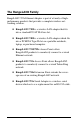
The RangeLAN2 Family RangeLAN2 792x Ethernet Adapter is part of a family of highperformance products that provides a complete wireless networking solution. ❑ RangeLAN2 7100 is a wireless LAN adapter that fits into a standard PC/AT ISA bus slot. ❑ RangeLAN2 7400 is a wireless LAN adapter which fits into a PCMCIA Type II slot on a portable notebook, laptop, or pen-based computer. ❑ RangeLAN2 7510/752x Access Points allow RangeLAN2 products to seamlessly connect to a wired Ethernet network.
System Requirements To begin using your RangeLAN2 792x Ethernet Adapter, you need the following minimum system requirements: ❑ An Ethernet-ready device such as a computer or Ethernet hub. ❑ At least one other RangeLAN2 product installed on the network. The Product Package Each RangeLAN2 792x Ethernet Adapter comes with: ❑ One (1) RangeLAN2 Ethernet Adapter. ❑ One (1) 1 dBi omnidirectional antenna. ❑ One (1) 12 Volt, 1 Amp power adapter. ❑ One (1) RS-232 serial cable. ❑ One (1) switch setting tool.
Figure 1 RangeLAN2 792x Ethernet Adapter Components 4
2. Quick Installation You may follow the quick installation and configuration steps, listed below, if all of the following conditions are true: ❑ You will use all of the software default values. ❑ You intend to use the Ethernet Adapter to connect an Ethernet-ready device to an existing RangeLAN2 network. ❑ The existing network uses a Domain number between 0 and 9. ❑ You do not intend to set Security IDs on your network. ❑ You do not intend to configure the Ethernet Adapter with an IP address.
Figure 2 Attachment of the RangeLAN2 Ethernet Adapter Antenna 2. Each RangeLAN2 792x Ethernet Adapter is preconfigured to use Domain 0. If the existing wireless network is not using Domain 0, use the Domain rotary switch on the underside of the RangeLAN2 Ethernet Adapter to set the Domain number to a value between 0 and 9. If the existing network is using a Domain number between 10 and 15, you must set the Domain number within the software configuration menu.
3. Plug the power supply into the RangeLAN2 Ethernet Adapter DC power jack, located on the rear panel, and plug the power supply into an AC outlet. Upon completing this step, the LED indicator on the top panel of the unit will glow yellow and then turn green, indicating that the unit is ready for operation. 4. Connect one end of a standard 10BASE-T cable to an Ethernet-ready device and the other end to the Ethernet Adapter.
Note: The RangeLAN2 Access Point is shipped with Filter Fixed Nodes set to “Filtering” by default. Unless you are using an Ethernet Access Point (model 7510, 7520, or 7521) with revision 1.4 or greater of the Access Point flash code image installed, this parameter must be set to “Not Filtering” in order for the Ethernet-ready device attached to the Ethernet Adapter to communicate with the wired network. For more information on this requirement, please refer to Chapter 11. 7.
3. Wireless Topologies RangeLAN2 products look and operate similar to Ethernet products. The only difference is that a radio replaces the wire between various nodes. This means that all of your existing applications that operate over Ethernet will work with RangeLAN2 without any special wireless networking software. Wireless products are typically used in several network topologies described in this chapter.
Infrastructure Many companies have an existing Ethernet or Token Ring LAN infrastructure and want to be able to extend that capability to wireless nodes. This is accomplished by attaching an Access Point to the wired LAN. This allows the wireless clients to access the network resources. Figure 4 Single Ethernet AP For larger environments, RangeLAN2 products support the ability to roam from one wireless cell to another while maintaining the same network connection.
Figure 5 Roaming on Ethernet LAN - Light Overlap With RangeLAN2’s multi-channel architecture, Access Points can be placed within the same cell area to increase the aggregate throughput supported by the network. In addition, the overlapping cells offer redundancy of coverage required in networks where downtime is not tolerable.
Figure 6 Roaming on Ethernet LAN- Heavy Overlap Each RangeLAN2 Access Point within a roaming network must be configured as a Master on a unique Channel/Subchannel pair, but all Access Points must have the same Domain number and Security ID.
Adapters or laptops with 7400 PC cards, are set to the same Domain and Security ID as the Access Points. As the RangeLAN2 mobile clients seamlessly switch from cell to cell, the network connectivity is preserved. The user can move freely between the RangeLAN2 Access Points in the network. When the roaming unit leaves the transmission range of one RangeLAN2 Access Point, the software automatically polls the other RangeLAN2 Access Point in the same Domain to continue the network connection.
Workgroup Concentrator In small networks, the RangeLAN2 Ethernet Adapter may be used as a workgroup concentrator to connect up to 8 Ethernet devices to a RangeLAN2 wireless network. However, the Ethernet Adapter can NOT support more than 8 devices on its Ethernet port, as shown in Figure 7. The Ethernet Adapter filters at a rate less than full Ethernet speed.
Since an Ethernet Adapter’s 10BaseT connector is wired to operate like a standard Ethernet cabling hub, you must use a 10BaseT cross-over cable to connect an Ethernet Adapter to a cabling hub. See Chapter 2 for information on the pinout specification for a 10BaseT cross-over cable. Note that the Ethernet Adapter does NOT support roaming. A wired network will support only one Ethernet Adapter acting as a Master. A wireless client can not roam between two Ethernet Adapters.
Repeating You have the option to enable or disable repeating. When repeating is enabled, the RangeLAN2 Ethernet Adapter, set as a Master, will repeat any signal coming from one Station and destined for another Station, when the two Stations are both within range of the Master, but not within range of one another. The advantage of repeating is the ability to double the effective range of the RangeLAN2 network.
4. Understanding the Hardware Rotary Switches The RangeLAN2 Ethernet Adapter is designed for easy configuration by setting two rotary switches located on the bottom of the unit. The rotary switches are shown in Figure 9 below. Use the switch setting tool, enclosed in the product package, to change the position of the rotary switches. ❑ The Station/Master Switch allows the user to externally set the unit’s Station Type to either a Master or a Station within a wireless network.
Domain Switch Station/Master Switch Figure 9 Rotary Switches LED Indicators There are three LEDs on the top panel of the RangeLAN2 792x Ethernet Adapter: ❑ The Status LED on the right side (with the unit orientated so that you can read the Proxim logo), changes colors from yellow (initializing) to green (operational). This LED will blink red in a repeating pattern if a problem occurs with the unit during operation. See Chapter 11 for a further discussion of these patterns.
❑ The Radio LED in the center blinks yellow when the Ethernet Adapter is transmitting data packets over its radio. ❑ The Ethernet LED on the left side blinks green when the Ethernet Adapter is transmitting data over the 10BASET Ethernet port.
There are also four LEDs on the back panel of the RangeLAN2 792x Ethernet Adapter: ❑ The green “Master” LED, located between the DC power jack and the serial interface, is on steady when the unit is set as a Master. ❑ The yellow “Sync” LED, located between the DC power jack and the serial interface, is on steady when the unit is set as a Station and is synchronized to a Master.
Link LED Master LED Sync LED Override LED Figure 11 Back Panel LEDs 21
10BASE-T Connector Specification The 10BASE-T connector located on the back panel of the Ethernet Adapter (see Figure 11, above) is wired like a cabling hub and connects to any Ethernet Network Interface Card using a standard 10BaseT cable. Standard 10BASE-T specifications apply to the 10BASE-T interface of the Ethernet Adapter. No segment can exceed 100 meters. If you intend to plug the Ethernet Adapter directly into a cabling hub, you must use a 10BASE-T cross-over cable.
Serial Port Specification Figure 13 and the table below provide the specification of the nine (9) pin serial port located on the RangeLAN2 Ethernet Adapter. The Ethernet Adapter is wired as a standard DCE (Data Communication Equipment) device.
Figure 13 Serial Port Specification 24
Antenna Options The Ethernet Adapter is shipped with a standard directly-connected antenna. To install the antenna, screw it clockwise onto the antenna connector. Proxim sells several antenna alternatives, including higher gain omnidirectional and directional antennas. Each of these antennas ship with installation and mounting instructions. For information on additional antenna options, please contact your Proxim Sales Representative.
2.75” 2.
5. Software Configuration You need to configure the RangeLAN2 Ethernet Adapter using the software menus if any of the following conditions apply: ❑ You want to set Security IDs on your network or your existing network uses a Security ID. ❑ You want to set the Domain number to a value between 10 and 15. ❑ You want to assign the Ethernet Adapter an IP address. ❑ You need to change any of the software default values.
The Ethernet Adapter’s configuration menu should look like this: Type the number of the menu option and to view the submenus. Hit at any time to back up one menu. To simplify the menu options, all of the configuration menus will appear in a tree diagram format.
Ethernet Adapter M ain M enu Display Param eter Values Reset Param eters to Factory D efaults Radio Configuration M enu Advanced Configuration M enu View Statistics Dow nload New Softw are Version Reset the Ethernet Adapter Exit The following four chapters detail the sub-menus, shown above.
30
6. Radio Configuration Menu This section discusses the RangeLAN2 radio parameters that can be configured by the user.
Radio Parameters Menu The table below shows the range and default values for each of the radio software parameters: Parame te r Name Rang e De fault Do main 0-15, and "U" fo r Use Switch Use Switch Channe l * 1-15, and 0 fo r auto matic se le ctio n 0 Sub channe l * 1-15 1 Statio n Typ e Maste r, Statio n, and "U" fo r Use Switch Use Switch Maste r Name * 11 characte rs MASTER Se curity ID 20 characte rs b lank Enab le Re p e ating * Y/ N N MACOp timize * No rmal, Lig ht, Ve ry Lig
Please note that changes to these parameters will not take affect until either the radio or the Ethernet Adapter is reset. A RangeLAN2 Ethernet Adapter may be set as either a Master or a Station using the Station Type parameter within the configuration menu. You may also choose “U” for Use Switch to use the value specified by the Station/Master rotary switch. The rotary switch is set to Station by default. Proxim’s RangeLAN2 products are frequency hopping spread spectrum radios which communicate in the 2.
In order to establish communication, all Stations and the Master must be configured with the same Domain number. Radios on different Domains cannot communicate with each other. The Domain is a software filter which does not affect the actual radio frequency or the frequency hopping sequence. You may want to set everyone on your network to the same Domain. For larger wireless networks, use the Domain to establish roaming subnetworks throughout your building.
There are 15 independent Channels designated 1 through 15. This means that there are 15 different sequences of frequency hops. Each Channel is at a different frequency at a different time. To minimize interference, set each Ethernet Adapter acting as a Master within the same area to a different Domain and Channel. In networks with multiple Access Points, set each Access Point to a different Channel but the same Domain to facilitate roaming.
The optional Master Name parameter of up to 11 characters specifies an alphanumeric name to simplify the identification of each Master in your network. You may not have spaces in the name. This parameter is visible only when the Ethernet Adapter is set as a Master. To further improve the security of a wireless subnetwork, each unit requires the same Security ID to establish communication. The Security ID is used on all RangeLAN2 products and all Station Types.
However, be aware that by enabling the repeating feature, the network throughput will drop by as much as one-half when repeating occurs. This parameter is only visible when the Ethernet Adapter is configured as a Master. By default, Repeating is disabled. See Chapter 3 for more information on Repeating. The MAC Optimize parameter can help improve throughput for small networks.
The Roam Config parameter allows you to determine how quickly an Ethernet Adapter, set as a Station, will roam from one Master Access Point to another. In areas with many RangeLAN2 Access Points that provide heavy overlapping coverage, set this parameter to Fast to maintain high throughput for each of the wireless nodes. In most networks, set the Roam Config parameter to Normal. Wireless node throughput will not change noticeably, and an overabundance of RangeLAN2 Access Points is not required.
7. Advanced Configuration Menu Use these parameters to configure the advanced features of the RangeLAN2 Ethernet Adapter.
Advanced Parameters Parame te r Name Rang e De fault Se t IP Ad d re ss - 0.0.0.0 Fo rward ing Datab ase Tab le Time o ut 10 to 1,000,000 se co nd s 300 CPU Po we r Save Mo d e Y/ N No Echo Mo d e No ne , Simp le , and Te rminal Te rminal Te chnical Sup p o rt Ac c e s s N/A N/A Set IP Address allows you to assign the Ethernet Adapter a unique network IP address.
The CPU Power Save Mode parameter will reduce the amount of power drawn by the Ethernet Adapter during operation. This is a useful feature for customer who are powering the Ethernet Adapter with a battery. Note: Enabling the CPU Power Save Mode will reduce the Ethernet Adapter’s rate of data transfer. The Ethernet Adapter’s serial port supports three Echo Modes when configuring the unit through a terminal session: None, Simple, and Terminal.
42
8. Display Parameter Values The Ethernet Adapter displays all of the relevant parameters in one centralized location. By choosing “Display Parameter Values,” you can view the current and configured values for the Radio and Advanced parameters. Current values are already in use by the Ethernet Adapter. If the configured value is different from the current value, the Ethernet Adapter must be reset before the configured value takes effect and at that time, the configured value becomes the new current value.
E the rne t Ada pte r M a in M e nu D ispla y P a ra m e te r V a lue s R a dio Pa ra m e te rs D o m a in C ha nn e l S u bc ha n ne l S ta tion T y pe M a ste r N a m e R e pe a ting E na ble d M AC O ptim ize In a c tivity T im e out (se c .) R o a m C onfig. R oa m ing E na ble d Adva nc e d C onfigu ra tio n Pa ra m e te rs IP Addre ss Filte r T a b le T im e out (se c .
9. View Statistics You can obtain operating statistics for the RangeLAN2 Ethernet Adapter from the View Statistics menu.
Synchronized To Statistic This statistic displays the Master Name of the RangeLAN2 product, acting as a Master, to which the RangeLAN2 Ethernet Adapter is synchronized. If the Ethernet Adapter is set as a Master, it will be synchronized to itself and display its own Master Name. Ethernet Statistics This category displays information about the packets sent and received through the Ethernet Adapter's Ethernet port.
10. Performance Hints This section provides ideas for how to increase performance with Proxim wireless products. Microwave Ovens Microwave ovens operate in the same frequency band as RangeLAN2. Therefore, if you use a microwave within range of RangeLAN2 products, you may notice network performance degradation. However, both your microwave and your RangeLAN2 network will continue to function. Range Every environment is unique with different obstacles, barriers, materials, etc.
If you are interested in antenna options, contact your Proxim Sales Representative about antenna kits. Proper antenna placement can help improve range. Here are some guidelines: ❑ The antenna should be placed in a vertical position. ❑ Do not place a sheet of metal (like a filing cabinet) between two antennas. ❑ Two antennas that are communicating should be in the same plane. For example, do not lie one antenna on its side and have its partner standing upright.
11. Troubleshooting The RangeLAN2 792x Ethernet Adapter is designed to be very easy to install and operate. If you do experience difficulties, however, use the information in this chapter to help diagnose and solve problems. If you cannot resolve a problem, contact Proxim, as described in Appendix E, “How to Reach Technical Support.
prefix. Therefore, an Access Point will filter out packets destined for these devices, and these devices will not be able to communicate through the Access Points with the wired network. This is not an issue for Ethernet Access Points with revision 1.4 or greater of the flash code image installed.
Below is a summary for changing this parameter on each model: Model 7500: Uncheck the NON-RangeLAN2 Address Filter on the Filter Configuration page of the 7500's Configuration Tool. Model 7510/752x: No action is needed if the Access Point has revision 1.4 or greater of the flash code image installed. If the Access Point is using an earlier version of the flash code, set the Filter Fixed Nodes parameter to “Not Filtering” in the Filter Configuration Menu.
LED Error Codes The main power LED located on the top of the Ethernet Adapter will flash red in repeating patterns to indicate the following errors: 1 blink: Could not initialize Ethernet interface 2 blinks: Memory check failed 3 blinks: Software error 4 blinks: Failed to initialize the radio 5 blinks: Memory full 6 blinks: Ethernet interface error 7 blinks: Miscellaneous error If you see any of the above flashing sequences, first attempt to reset the Ethernet Adapter.
Commonly Asked Technical Support Questions Pro b le m/Symp to m Que stio n Po ssib le So lutio n/Answe r Chap te r in Use r' s Guid e Ho w d o I kno w if the Ethe rne t Ad ap te r is using the the se tting s o n the switch o r the se tting s se t b y the co nfig uratio n so ftware ? If e ithe r the Do main o r Statio n Typ e ro tary switch have b e e n o ve rrid d e n b y the co nfig uratio n so ftware , the ye llo w o ve rrid e LED, lo cate d o n the b ack sid e o f the unit, will illuminate .
Pro b le m/Symp to m Que stio n Po ssib le So lutio n/Answe r Chap te r in Use r' s Guid e I can' t e stab lish a wire le ss co nne ctio n with the Ethe rne t Ad ap te r. Ve rify that the Ethe rne t Ad ap te r is se t to the same Do main and Se curity ID as the o the r Rang e LAN2 p ro d ucts in yo ur ne two rk. 6 I have a wire le ss co nne ctio n, b ut my Ethe rne t-re ad y d e vice can' t co mmunicate with the ne two rk. 1.
A. Menu Structure E th e rn e t Ad a p te r M a in M e n u D isp la y Pa ra m e te r V a lu e s R a d io Pa ra m e te rs D o m a in Channel Subchannel S ta tio n T y p e M a ste r N a m e R e p e a tin g E n a b le d M AC O p tim ize In a c tivity T im e o u t (se c .) R o a m C o n fig . R o a m in g E n a b le d Ad va n c e d C o n fig u ra tio n Pa ra m e te rs IP Ad d re ss F ilte r T a b le T im e o u t (se c .
E thernet Ada pte r M ain M e nu D isplay Pa ram eter V a lues R eset Param ete rs to Fac tory D efa ults R adio Configuration M enu Dom ain Cha nnel S ubcha nnel S ta tion T ype M a ster Na m e S ec urity ID E nable R ep eating M a c Optim ize Ina ctivity T im eou t Roa m C onfig Roa m ing E nable d Re set R adio Advanc ed C onfigura tion M e nu V iew S tatistic s D ow nload N ew S oftw are V e rsion R eset the E the rne t Adapter E xit Dotted Line - Visible w hen configured as a M aster Dash
Eth ernet Ad ap ter M ain M en u D isp lay P aram eter Valu es R eset P aram eters to F acto ry D efau lts R ad io C o n fig u ratio n M en u Ad van ced C o n fig u ratio n M en u Set IP Ad d ress F o rw ard in g D atab ase T ab le T im eo u t C P U P o w er S ave M o d e Ech o M o d e T ech n ical Su p p o rt Access View S tatistics D o w n lo ad N ew So ftw are Versio n R eset th e Eth ern et Ad ap ter Exit 57
Ethern et Adapter M ain M en u D isp lay Param eter Valu es R eset Param eters to F acto ry D efaults R adio C o nfig uratio n M enu Advan ced C o n fig u ration M en u View Statistics Syn ch ro nized T o Eth ern et Statistics Packets Sent Packets R eceived C o llision s F ram e Alig n Erro rs C R C Errors M issed Packets R eceive O verflo w Packets F iltered R ad io Statistics Packets T ran sm itted Packets R eceived D o w n load N ew Softw are Version R eset th e Eth ern et Ad ap ter Exit 5
B. Parameters Radio Parameters Parame te r Name Rang e De fault Do main 0-15, and "U" fo r Use Switch Use Switch Channe l * 1-15, and 0 fo r auto matic se le ctio n 0 Sub channe l * 1-15 1 Statio n Typ e Maste r, Statio n, and "U" fo r Use Switch Use Switch Maste r Name * 11 characte rs MASTER Se curity ID 20 characte rs b lank Enab le Re p e ating * Y/ N N MACOp timize * No rmal, Lig ht, Ve ry Lig ht, and Auto Auto Inactivity Time o ut t 0 fo r no time o ut and 1, 2, 3, ...
Advanced Configuration Parameters Parame te r Name Rang e De fault Se t IP Ad d re ss - 0.0.0.
C. Procedure for Downloading New Software At some point in the future, you may need to upgrade the RangeLAN2 Ethernet Adapter software. To do this, choose the Download New Software Version option from the Main Menu. You need to use the XMODEM protocol to complete the download. Commonly used serial communication programs, such as Hyperterminal and Procomm Plus, support the XMODEM protocol. The steps for downloading a new image are: 1.
Note: Do not choose the "Download New Software Version" menu item unless you are prepared to perform a software download to the device. Once you proceed past the warning messages, there is no way to exit the download process. The unit will not become operational again until after a download of software to the Ethernet Adapter has been successfully completed.
D. Glossary 10BASE-T Cross-over Cable — A standard 10BASE-T Ethernet cable with pins 1 & 3 and 2 & 6 crossed to allow two Ethernet devices with the same pin specification to communicate directly with one another. Access Point — An internetworking device that seamlessly connects wired and wireless networks together. Bandwidth — The size (in Hertz) of the frequency range that a signal transmission occupies. Typical narrow band signals occupy a 25 KHz bandwidth. The RangeLAN2 signal occupies a 1 MHz bandwidth.
Filtering — An action performed by an Ethernet device, such as a bridge, switch, or router, which excludes an Ethernet packet from being passed from one subnetwork to another based upon the packet's destination, source, or packet type. Frequency Hopping — A spread spectrum technique by which the band is divided into a number of channels and the transmissions hop from channel to channel in a pre-specified sequence.
E.
F. U.S. Specifications The following technical specification is for reference purposes only. Actual product's performance and compliance with local telecommunications regulations may vary from country to country. Proxim, Inc. will only ship products that are type approved in the destination country. Network Interface Ethernet 10BaseT (Twisted-Pair) Data Rate 1.
Index 10BASE-T 7, 15, 22, 66 Cross-over Cable 15, 22 A Access Point. See RangeLAN2: Access Point Ad Hoc 9, 33 Antenna 3, 5, 25, 47, 66 C Channel 12, 32, 34–35 Collisions 46 Configuration Menu 28, 29 Advanced Configuration Menu. See Advanced Configuration Menu Displaying Menu 27 Parameter Tables 59–60 Radio Configuration Menu. See Radio Configuration Menu Configured Parameter Value 43 CPU Power Save Mode 41 CRC Errors 46 Cross-over Cable.
F FCC ii, 66 Filter Fixed Nodes. See Fixed Node Filtering Filtering 64 Fixed Node Filtering 49–51 Forwarding Database Table Timeout 40 Frame Align Errors 46 Frequency Hopping. See Spread Spectrum: Frequency Hopping I Inactivity Timeout 32, 37 Installation How to Obtain Help 49 IP Address 27, 40, 64 L LED Error Codes 52 LEDs 18 Link LED 7, 20. See also LEDs M MAC Optimize 32, 37 Macintosh 9 Master 12, 15, 16, 17, 20, 32, 33. See also Station Type Master LED 20, 21.
R Radio Configuration Menu 31–38. See also Configuration Menu Radio LED 19. See also LEDs Radio Statistics 46 Range 47 RangeLAN2 1, 3, 9, 10, 11, 14, 66 Access Point 2, 10, 11, 12, 13, 14, 33, 38, 49–51 Extension Point 2, 38 Family 1, 2 RangeLAN2 Access Point 12, 13, 14 Receive Overflow 46 Repeating 16, 32, 36 Reset Radio 32 RMA i Roam Config 32, 38 Roaming 10, 12, 13, 32, 34, 38, 50 Rotary Switch 17, 20 Domain 17 Station/Master 33.
Temperature Operating 66 Terminal 27, 61 Token Ring 2, 10, 51 U U.S.