9800 Martel Road Lenoir City, TN 37772 www.ps-engineering.com PMA6000 PMA6000S PMA6000M PMA6000M-S PMA6000C PMA6000S-C PMA6000M-C PMA6000M-S-C Audio Selector Panel with Intercom System and Audio Selector Panel with High-fidelity Stereo Intercom System Installation and Operation Manual Flying never sounded so good™ FAA-Approved TSO C35d TSO C50c Document P/N 200-066-0006 Revision 6, March 2005 PS Engineering, Inc.
PS Engineering PMA6000 Series Audio Selector Panel and Intercom System Installation Manual Table of Contents Section I GENERAL INFORMATION................................................................................................ 1-1 1.1 INTRODUCTION.................................................................................................................... 1-1 1.2 SCOPE .............................................................................................................................
PS Engineering PMA6000 Series Audio Selector Panel and Intercom System Installation Manual 3.5 Split Mode (6000C, 6000MC, 6000SC, 6000MSC) ................................................................ 3-3 3.6 Intercom ................................................................................................................................... 3-3 3.6.1 Volume Control, Monaural (6000, 6000M, 6000C, 6000MC)............................................ 3-3 3.6.
PS Engineering PMA6000 Series Audio Selector Panel and Intercom System Installation Manual Section I GENERAL INFORMATION 1.1 INTRODUCTION The PMA6000 family of Audio Selector Panels are revolutionary products. Never before has there been so much capability and utility in such a compact package. These units are designed for ease of use and installation, as well as to facilitate cockpit resource management and improve passenger entertainment.
PS Engineering PMA6000 Series Audio Selector Panel and Intercom System Installation Manual An optional 3-light Marker Beacon receiver is integral to the PMA6000M, PMA6000MS PMA6000MC and PMA6000M-S-C. This provides the necessary Marker Beacon light and audio indications necessary for an Instrument Landing System (ILS) approach.
PS Engineering PMA6000 Series Audio Selector Panel and Intercom System Installation Manual 1.5 SPECIFICATIONS GENERAL SPECIFICATION CHARACTERISTIC TSO COMPLIANCE: Marker Beacon: C35d, Class A Audio Selector/Intercom: C50c, Class A APPLICABLE DOCUMENTS: RTCA DO-160b, RTCA DO-170 and RTCA DO-143 ENVIRONMENTAL Qualifications: A1D1/CAMXXXXXXXBBBBAAX Temperature Range: Operating: -20°C to +55°C Storage: -40°C to +85°C Altitude: Up to 50,000 feet in an non-pressurized area of the cockpit.
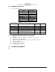
PS Engineering PMA6000 Series Audio Selector Panel and Intercom System Installation Manual 1.6 EQUIPMENT SUPPLIED A. 1 ea. of the following units: Model PMA6000 PMA6000S PMA6000M PMA6000M-S PMA6000C PMA6000S-C PMA6000M-C PMA6000M-S-C Tray B. PMA6000 Installation Kit: Part Number 120-425-4402 120-425-4401 120-425-4400 425-001-0001 701-015-0015 200-066-0003 1.
PS Engineering PMA6000 Series Audio Selector Panel and Intercom System Installation Manual Section II -Installation 2.1 GENERAL INFORMATION 2.1.1 SCOPE This section provides detailed installation and interconnect instructions for the PS Engineering PMA6000Series Audio Selector Panel/Intercom System and PMA6000M-Series Audio Selector Panel/Intercom System with internal Marker Beacon.
PS Engineering PMA6000 Series Audio Selector Panel and Intercom System Installation Manual 2.3.2 Mounting Requirements The PMA6000 must be rigidly mounted to the instrument panel of the aircraft structure and within view and reach of the pilot position(s). Installation must comply with FAA Advisory Circular AC 43.13-2A. The unit may be mounted in any area where adequate clearance for the unit and associated wiring bundle exist.
PS Engineering PMA6000 Series Audio Selector Panel and Intercom System Installation Manual ference is possible. The PMA6000s were designed in a RFI hardened chassis and have internal Electromagnetic Interference (EMI) filters on all inputs and outputs. Ground loop noise occurs when there are two or more ground paths for the same signal (i.e., airframe and ground return wire). Large cyclic loads such as strobes, inverters, etc.
PS Engineering PMA6000 Series Audio Selector Panel and Intercom System Installation Manual the single entertainment device and entertainment input #1. This will allow the pilot and copilot to decide if they hear entertainment while in the Crew mode. Local oscillators and internal signals from some entertainment equipment can cause undesired interference with other aircraft systems. Before takeoff, operate the entertainment devices to determine if there is any adverse effect within the aircraft systems.
PS Engineering PMA6000 Series Audio Selector Panel and Intercom System Installation Manual NOTICE: To reduce the amount of heat dissipated in the audio selector panel, when used in a 28 Volt aircraft, a 15 Ω, 15 Watt dropping resistor (p/n 701-015-1501) must be installed in series with the power input. 2.4.
PS Engineering PMA6000 Series Audio Selector Panel and Intercom System Installation Manual Bottom connector pin T is an unswitched and unmuted audio input. This audio is always presented to the headphones and speaker, regardless of the audio panel audio selections. This input can be use for critical warnings, such as radio altimeter warnings. 2.4.13 Intercom The top connector is for the intercom function.
PS Engineering PMA6000 Series Audio Selector Panel and Intercom System Installation Manual Adjustment Clockwise Results In Cabin Speaker Level Increase Speaker Volume Marker Beacon Level Decrease Marker Volume MKR Gain Increase overall sensitivity MKR High Sense Increase sensitivity MKR Low Sense Increase Sensitivity Pass. Headphone (Mono or L & R) Louder To make the necessary adjustments, use a small jeweler's slotted screwdriver.
PS Engineering PMA6000 Series Audio Selector Panel and Intercom System Installation Manual W a r n i n g : D o n o t o v e r - t i g h te n t h e l o c k d o w n s c r e w w h i l e i n s t a l l i n g t h e u n i t i n tray. Internal damage will result. 2.9 Post Installation Checkout 2.9.1 Required Test Equipment In order to return an aircraft to service after installation of the PMA6000-series with marker beacon receiver, the installer must have access to a Marker Beacon signal generator: a.
PS Engineering PMA6000 Series Audio Selector Panel and Intercom System Installation Manual 2.10 1. 2. 3. Marker Checkout, 6000M, 6000M-C, 6000M-S Only Connect a ramp generator at the antenna end of the marker coax. With the unit under test in HI sensitivity, verify that a 150 µVolts, modulated 95% with 1300 Hz signal will illuminate the amber (M) marker light, and that marker audio is present in the headphones when the Marker Audio (M) pushbutton has been depressed.
PS Engineering PMA6000 Series Audio Selector Panel and Intercom System Installation Manual 2.11 Final Inspection. Verify that the wiring is bundled away from all controls and no part of the installation interferes with aircraft control operation. Move all controls through their full range while examining the installation to see that no mechanical interference exists. Verify that the cables are secured to the aircraft structure in accordance with good practices, with adequate strain relief.
PS Engineering PMA6000 Series Audio Selector Panel and Intercom System Installation Manual Section III OPERATION GENERAL INFORMATION 3.1 SCOPE This section provides detailed operating instructions for the PS Engineering PMA6000, PMA6000S, PMA6000M, PMA6000M-S, PMA6000C, PMA6000S-C, PMA6000M-C, and PMA6000M-S-C Audio Selector Panel/Intercom Systems. Please read it carefully before using the equipment so that you can take full advantage of its capabilities.
PS Engineering PMA6000 Series Audio Selector Panel and Intercom System Installation Manual 3.3 Mic Selector Switch (Fail Safe Operation) Figure 3-2 Mic Selector Unit power is turned on and off by the Mic selector switch. In the OFF or "FAILSAFE" position, the pilot is connected directly to Com 1 allowing transmit and receive capability regardless of unit condition. Any time power is removed or turned OFF, the audio selector will be placed in the fail-safe mode.
PS Engineering PMA6000 Series Audio Selector Panel and Intercom System Installation Manual 3.5 Split Mode (6000C, 6000MC, 6000SC, 6000MSC) Operation is identical to section 3.4 (above) except turning the mic selector clockwise to the COM 3 position places both pilot and copilot on Com 3, and exits the split mode. All selected audio inputs and intercom function return. Note: In all PMA6000s, Split Mode turns off all other (Nav, ADF, etc.)selected audio to pilot and copilot.
PS Engineering PMA6000 Series Audio Selector Panel and Intercom System Installation Manual with the same intercom. The user can adjust the trip level of the VOX to fit the individual's voice and mic, which helps eliminate the frustration of clipping the first syllables. With the engine running, set the VOX control knob by slowly rotating the SQL control knob clockwise until you no longer hear the engine noise in the headphones.
PS Engineering PMA6000 Series Audio Selector Panel and Intercom System Installation Manual 3.6.5.3 Entertainment Input The audio selector panel has provisions for up to two separate entertainment input devices. Which device is heard is determined by the position of the three position mode switch located in the center of the intercom section of the audio panel. (See Table 3-1 for overview.) While in the ISO (Isolate) mode, only the copilot and the four passengers will hear entertainment device #1.
PS Engineering PMA6000 Series Audio Selector Panel and Intercom System Installation Manual The recorder function is automatic. Pressing the momentary switch will cause the last message to play (incoming radio and transmit sidetone). This will be heard in the pilot headset only. To hear older messages, push the playback button repeatedly to “back up” the recorder, until the desired message is heard. The recorder is a continuous loop, and newest ones will overwrite the oldest messages.
PS Engineering PMA6000 Series Audio Selector Panel and Intercom System Installation Manual Section IV- Warranty and Service 4.1 Warranty In order for the factory warranty to be valid, the installations in a certified aircraft must be accomplished by an FAA- certified avionics shop and authorized PS Engineering dealer. An FAA Form 337 must also be accompanied by the warranty card for this warranty to be in effect.
PS Engineering PMA6000 Series Audio Selector Panel and Intercom System Installation Manual Appendix A External PTT Hook Up Part of the installation includes the installation of PTT (Push To Talk) switches that allow the use of your aircraft radio for communications transmissions. There are three configurations that can be used, you must select the case that best fits your installation. NOTE: Only the person who presses their PTT switch will be heard over the radio.
PS Engineering PMA6000 Series Audio Selector Panel and Intercom System Installation Manual Appendix B- Installation Drawing Cutout size for front mount installation 1.315 in (33.4 mm) 6.31in (160.3 mm) 6.65 in (167 mm) Side View 0.60 in (15.25 mm) CG 0.35 in (8.9 mm) 1.31 in (33.27 mm) 3.00 in (76.2 mm) 5.25 in (133.4 mm) 0.8 in (20.3 mm) 6.28 in (159.5 mm) Rear View Weight: 1.5 lb with tray and connectors ( .
PS Engineering PMA6000 Series Audio Selector Panel and Intercom System Installation Manual Appendix C Bottom Connector wiring, Mono and Stereo (see note 9) BOTTOM CONNECTOR PMA6000 9 Com 1 Audio Hi Communications Transceiver #1 Com 1 Lo P R 19 L Com 1 Mic Audio Hi Com 1 Mic Key Com 1 Spr Load Com 1 Spr Load Com 1 SPR Load See Notes 6, 8 10 Com 2 Audio Hi Communications Transceiver #2 Com 2 Lo H V 16 M J Com 2 Mic Audio Hi Com 2 Mic Key Com 2 SPR Load Com 2 Spr Load Com 2 Spr Load Communicat
PS Engineering PMA6000 Series Audio Selector Panel and Intercom System Installation Manual Appendix D Top Connector wiring (Mono), PMA6000, PMA6000C, PMA6000M, PMA6000M-C Top Connector PMA6000 (monaural) 3 C Copilot Phones Hi Notes: Copilot Phones Lo 1 Pass. Phones Hi A Pass. Phones Lo 5 E Pass. Mic Hi 6 F Pass. Mic Hi Pass. Mic Lo 7 H 8 J 1. All shields should be grounded at audio panel only. other end remains floating. 2. All phone and mic jacks must be floating from ground. 3.
PS Engineering PMA6000 Series Audio Selector Panel and Intercom System Installation Manual Appendix E Top Connector wiring, (Stereo) PMA6000S, PMA6000MS, PMA6000MS-C PMA6000M-S-C TOP CONNECTOR (Stereo) 1 Pilot Phones (L) -see bottom connector. 3 2 B Notes: Copilot Phones (R) 1. All shields should be grounded at audio panel only. other end remains floating. 2. All phone and mic jacks must be floating from ground. 3. All wiring to conform to MIL 22750 or 27500. 4.
PS Engineering PMA6000 Series Audio Selector Panel and Intercom System Installation Manual Appendix F -Instructions for Continuing Airworthiness and FAA Form 337 Sample ICA Checklist for PS Engineering Audio Panels: Section 1 Introduction Item 2 Description 3 4 5 6 Controls Servicing Maintenance Instructions Troubleshooting 7 Removal and replacement information 8 9 10 11 12 13 14 15 16 Diagrams Special Inspection Requirements Protective Treatments Structural Data Special Tools Not Applicable Reco
PS Engineering PMA6000 Series Audio Selector Panel and Intercom System Installation Manual Appendix G RTCA DO160B Environmental Qualification Form Audio Selector Panel/Intercom/Marker Beacon Receiver Part Number: 6000, 6000M, 6000MC, 6000S, 6000MS 6000M-S-C FAA TSO Number: C50c, C35b Class A Manufacturer: PS Engineering Incorporated 9800 Martel Road Conditions Lenoir City TN 37772 Section Conducted Tests Temperature and Altitude Low Temperature High Temperature Altitude 4.0 4.5.1 4.5.2 4.6.