9800 Martel Road Lenoir City, TN 37772 www.ps-engineering.com PMA6000 PMA6000M PMA6000C PMA6000M-C Audio Selector Panel with Intercom System and Marker Beacon Receiver Installation and Operation Manual Flying never sounded so good™ FAA-Approved TSO C35d TSO C50c Document P/N 200-066-0100 Revision 1, March 2005 PS Engineering, Inc. 2005 © Copyright Notice Any reproduction or retransmittal of this publication, or any portion thereof, without the expressed written permission of PS Engineering, Inc.
PS Engineering PMA6000 Series Audio Selector Panel and Intercom System Installation Manual Table of Contents Section I GENERAL INFORMATION................................................................................................ 1-1 1.1 INTRODUCTION.................................................................................................................... 1-1 1.2 SCOPE .............................................................................................................................
PS Engineering PMA6000 Series Audio Selector Panel and Intercom System Installation Manual 3.5 Split Mode (6000C, 6000MC) ................................................................................................. 3-2 3.6 Intercom ................................................................................................................................... 3-3 3.6.1 Volume Control, Monaural (6000, 6000M, 6000C, 6000MC)............................................ 3-3 3.6.
PS Engineering PMA6000 Series Audio Selector Panel and Intercom System Installation Manual Section I GENERAL INFORMATION 1.1 INTRODUCTION The PMA6000 family of Audio Selector Panels are revolutionary products. Never before has there been so much capability and utility in such a compact package. These units are designed for ease of use and installation, as well as to facilitate cockpit resource management and improve passenger entertainment.
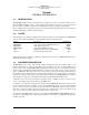
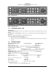
PS Engineering PMA6000 Series Audio Selector Panel and Intercom System Installation Manual Figure 1-1 PMA6000M Figure 1-2 PMA6000M-C 1.4 APPROVAL BASIS - FAA TSO Approval. The PMA6000, PMA6000C and Audio Selector Panels are FAA approved under TSO C50c (Audio Amplifiers). The PMA6000M and PMA6000M-C are FAA approved under TSO C50c and TSO C35d (Marker Beacon Receivers). All systems comply with RTCA DO-143, DO-160b and DO-170. Operation is subject to the following conditions: 1.
PS Engineering PMA6000 Series Audio Selector Panel and Intercom System Installation Manual Unswitched Inputs: 2 (TEL Ringer, Altimeter DH) Transmitter Selections: 5 (Com 1, Com 2, Com1/2, Com2/1, TEL/Com1) on PMA6000, , PMA6000M (Com 1, Com 2, Com1/2, Com2/1, Com 3) on PMA6000C, PMA6000M-C Speaker Impedance: 4Ω Headphone Impedance: 150 - 1000 Ω Headphone Output: 45 mW each headset with no clipping Microphone Impedance: 150 - 600 Ω Intercom Positions: 6 places Music Inputs: 2 Music Muting: >50 dB "Soft Mute
PS Engineering PMA6000 Series Audio Selector Panel and Intercom System Installation Manual 1.7 EQUIPMENT REQUIRED BUT NOT SUPPLIED A. B. C. D. E. F. G. H. I. 1.8 Speaker, 4 Ω Headphones, mono, up to 6 as required Microphones, up to 6 as required Marker Antenna (75 MHz, VSWR <1:1.5, and appropriate for the airspeed) Interconnect Wiring Headphone Jacks (Up to 6 as required) Microphone Jacks (Up to 6 as required) Circuit Breaker: 1 ea. 2 amp. PMA6000 Installation Manual, P/N 200-066-0100, available at www.
PS Engineering PMA6000 Series Audio Selector Panel and Intercom System Installation Manual Section II -Installation 2.1 GENERAL INFORMATION 2.1.1 SCOPE This section provides detailed installation and interconnect instructions for the PS Engineering PMA6000Series Audio Selector Panel/Intercom System and PMA6000M-Series Audio Selector Panel/Intercom System with internal Marker Beacon.
PS Engineering PMA6000 Series Audio Selector Panel and Intercom System Installation Manual 2.3.2 Mounting Requirements The PMA6000 must be rigidly mounted to the instrument panel of the aircraft structure and within view and reach of the pilot position(s). Installation must comply with FAA Advisory Circular AC 43.13-2A. The unit may be mounted in any area where adequate clearance for the unit and associated wiring bundle exist.
PS Engineering PMA6000 Series Audio Selector Panel and Intercom System Installation Manual Radiated signals can be a factor when low level microphone signals are "bundled" with current carrying power wires. Keep these cables physically separated. It is very important that you use insulated washers to isolate the ground return path from the airframe to all headphone and microphone jacks.
PS Engineering PMA6000 Series Audio Selector Panel and Intercom System Installation Manual CASE I: PTT is built into both pilot and copilot yokes. CASE II: PTT is in pilot yoke only. This configuration requires a modified external PTT switch plugged into the copilot's microphone jack. (See Appendix A). When the copilot's PTT is pressed, the intercom switches the mic audio from pilot to copilot mic. CASE III: No built in PTT.
PS Engineering PMA6000 Series Audio Selector Panel and Intercom System Installation Manual 2.4.9 Speaker Loads Certain VHF Nav/Comms, such as King KX170-series have internal speaker amplifiers. These are not used with a PMA6000, but must be loaded to prevent unit failure. Connect the speaker output from the Nav/Com to the appropriate load on the PMA6000 (bottom connector 19 and L for COM 1, etc). 2.4.10 PA Mute Bottom connector pin 18 is a TTL logic output that is pulled low during PTT operation.
PS Engineering PMA6000 Series Audio Selector Panel and Intercom System Installation Manual A radio signal of more than 1 VRMS is needed to trigger the IRS. Therefore, if the IRS does not seem to be recording, increase the aircraft radio volume slightly. 2.5 Adjustments The PMA6000 is factory adjusted to accommodate the typical requirements for most aircraft configurations. There are three adjustments however, that will allow the installer to tailor the specific functions.
PS Engineering PMA6000 Series Audio Selector Panel and Intercom System Installation Manual W a r n i n g : D o n o t o v e r - t i g h te n t h e l o c k d o w n s c r e w w h i l e i n s t a l l i n g t h e u n i t i n tray. Internal damage will result. 2.9 Post Installation Checkout 2.9.1 Required Test Equipment In order to return an aircraft to service after installation of the PMA6000-series with marker beacon receiver, the installer must have access to a Marker Beacon signal generator: a.
PS Engineering PMA6000 Series Audio Selector Panel and Intercom System Installation Manual 2.9.4 Operational Checkout, 3rd Com version (6000C and 6000M-C) 1. Complete steps 1 to 10, above. 2. Rotate the mic selector switch to the COM 3 position. Verify that the pilot communicates on the transceiver in the Com3 position and the copilot on Com 1. 3. Verify proper operation of all receiver sources by selecting them using the keypad.
PS Engineering PMA6000 Series Audio Selector Panel and Intercom System Installation Manual Section III OPERATION GENERAL INFORMATION 3.1 SCOPE This section provides detailed operating instructions for the PS Engineering PMA6000, PMA6000M, PMA6000C, and PMA6000M-C Audio Selector Panel/Intercom Systems. Please read it carefully before using the equipment so that you can take full advantage of its capabilities.
PS Engineering PMA6000 Series Audio Selector Panel and Intercom System Installation Manual the person who presses their Push To Talk (PTT), will be heard over the aircraft radio. Turning the rotary switch to the COM 2 position will place pilot and copilot on Com 2. The PMA6000-Series has an automatic selector mode. Audio from the selected transceiver is automatically heard in the headsets and speaker (when selected).
PS Engineering PMA6000 Series Audio Selector Panel and Intercom System Installation Manual 3.6 Intercom 3.6.1 Volume Control (6000, 6000M, 6000C, 6000MC) The pilot volume control knob adjusts the loudness of intercom and music in the pilot’s headphones only. It has no effect on selected radio audio levels. The copilot volume control adjusts the loudness of the intercom and music in the copilot headset only. The passenger volume is factory set at a comfortable level.
PS Engineering PMA6000 Series Audio Selector Panel and Intercom System Installation Manual 3.6.3.2 Entertainment Input The audio selector panel has provisions for up to two separate entertainment input devices. Which device is heard is determined by the position of the three position mode switch located in the center of the intercom section of the audio panel. (See Table 3-1 for overview.) While in the ISO (Isolate) mode, only the copilot and the four passengers will hear entertainment device #1.
PS Engineering PMA6000 Series Audio Selector Panel and Intercom System Installation Manual The recorder function is automatic. Pressing the momentary switch will cause the last message to play (incoming radio and transmit sidetone). This will be heard in the pilot headset only. To hear older messages, push the playback button repeatedly to “back up” the recorder, until the desired message is heard. The recorder is a continuous loop, and newest ones will overwrite the oldest messages.
PS Engineering PMA6000 Series Audio Selector Panel and Intercom System Installation Manual the need for the avionics shop to reduce the sensitivity in the field so as to prevent early detection of the marker beacons. If your particular installation requires more or less sensitivity, please call the factory for details on how to adjust the receiver sensitivity in the field. 200-066-0100 Page 3-6 Rev.
PS Engineering PMA6000 Series Audio Selector Panel and Intercom System Installation Manual Section IV- Warranty and Service 4.1 Warranty In order for the factory warranty to be valid, the installations in a certified aircraft must be accomplished by an FAA- certified avionics shop and authorized PS Engineering dealer. An FAA Form 337 must also be accompanied by the warranty card for this warranty to be in effect.
PS Engineering PMA6000 Series Audio Selector Panel and Intercom System Installation Manual Appendix A External PTT Hook Up Part of the installation includes the installation of PTT (Push To Talk) switches that allow the use of your aircraft radio for communications transmissions. There are three configurations that can be used, you must select the case that best fits your installation. NOTE: Only the person who presses their PTT switch will be heard over the radio.
PS Engineering PMA6000 Series Audio Selector Panel and Intercom System Installation Manual Appendix B- Installation Drawing Cutout size for front mount installation 1.315 in (33.4 mm) 6.31in (160.3 mm) 6.65 in in (167 mm) Side View 0.60 in in (15.25 mm) CG 0.35 in in (8.9 mm) 1.31 in in (33.27 mm) 3.00 in in (76.2 mm) 5.25 in in (133.4 mm) 0.8 in in (20.3 mm) 6.28 in in (159.5 mm) Rear View Weight: 1.5 lb with tray and connectors ( .
PS Engineering PMA6000 Series Audio Selector Panel and Intercom System Installation Manual Appendix C Bottom Connector wiring, (see note 9) BOTTOM CONNECTOR PMA6000 9 Com 1 Audio Hi Communications Transceiver #1 Com 1 Lo P R 19 L Com 1 Mic Audio Hi Com 1 Mic Key Com 1 Spr Load Com 1 Spr Load Com 1 SPR Load See Notes 6, 8 10 Com 2 Audio Hi Communications Transceiver #2 Com 2 Lo H V 16 M J Com 2 Mic Audio Hi Com 2 Mic Key Com 2 Spr Load Com 2 Spr Load Com 2 SPR Load Com 3 Audio Hi Communicati
PS Engineering PMA6000 Series Audio Selector Panel and Intercom System Installation Manual Appendix D Top Connector wiring (Mono), PMA6000, PMA6000C, PMA6000M, PMA6000M-C Top Connector PMA6000 (monaural) Notes: 1. All shields should be grounded at audio panel only. other end remains floating. 2. All phone and mic jacks must be floating from ground. 3. All wiring to conform to MIL 22750 or 27500. 4. PMA6000 with serial number beginning with "M" will have PTT intercom capability. 5.
PS Engineering PMA6000 Series Audio Selector Panel and Intercom System Installation Manual Appendix F -Instructions for Continuing Airworthiness and FAA Form 337 Sample ICA Checklist for PS Engineering Audio Panels: Section 1 Introduction Item 2 Description 3 4 5 6 Controls Servicing Maintenance Instructions Troubleshooting 7 Removal and replacement information 8 9 10 11 12 13 14 15 16 Diagrams Special Inspection Requirements Protective Treatments Structural Data Special Tools Not Applicable Reco
PS Engineering PMA6000 Series Audio Selector Panel and Intercom System Installation Manual Appendix G RTCA DO160B Environmental Qualification Form Audio Selector Panel/Intercom/Marker Beacon Receiver Part Number: 6000, 6000M, 6000MC FAA TSO Number: C50c, C35b Class A Manufacturer: PS Engineering Incorporated 9800 Martel Road Conditions Lenoir City TN 37772 Section Conducted Tests Temperature and Altitude Low Temperature High Temperature Altitude 4.0 4.5.1 4.5.2 4.6.