
Installation manual

PS Engineering
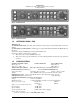
PMA6000 Series Audio Selector Panel and Intercom System
Installation Manual
200-066-0100 Page 1-3 Rev. 1, March 2005
Unswitched Inputs: 2
(TEL Ringer, Altimeter DH)
Transmitter Selections: 5
(Com 1, Com 2, Com1/2, Com2/1, TEL/Com1)
on PMA6000, , PMA6000M
(Com 1, Com 2, Com1/2, Com2/1, Com 3)
on PMA6000C, PMA6000M-C
Speaker Impedance: 4 Ω
Headphone Impedance: 150 - 1000 Ω
Headphone Output: 45 mW each headset with no clipping
Microphone Impedance: 150 - 600 Ω
Intercom Positions: 6 places
Music Inputs: 2
Music Muting: >50 dB "Soft Mute" when Com or intercom active.
Distortion: <1% THD @ 45 mW into 150Ω
Mic Freq. Response, ±3 dB: 350 Hz - 6000 Hz
Music Freq. Response, ±3 dB: 200 Hz - 15 kHz
MARKER BEACON RECEIVER: (PMA6000M, PMA6000M-S, PMA6000M-C, PMA6000M-S-C
Only)
Frequency: 75 MHz Crystal Controlled
Sensitivity:
Low: 450 µVolts (Hard)
Factory adjusted to 1400µV (Soft)
High: 160 µVolts (Hard)
Factory adjusted to 150µV (Soft)
Selectivity: -6 dB at 110 kHz -40 dB at 120 kHz
External Lamp Output: 9.0 (+/- 0.5) VDC Positive when active, max. current 125 mA
MM Sense: Active high (4.7 VDC +/- 0.5V) during Middle Marker acqui-
sition, for autopilot use.
1.6 EQUIPMENT SUPPLIED
A. 1 ea. of the following units:
Model Part Number
PMA6000 6000
PMA6000M 6000M
PMA6000C 6000C
PMA6000M-C 6000MC
Tray 430-004-0001
B. PMA6000 Installation Kit:
Part Number Description Quantity
120-425-4401 Top Connector, (key 2/3) 1
120-425-4400 Bottom Connector (key 7/8) 1
425-001-0001 Gold Plated Crimp Pins 75
701-015-0015 15 Watt Dropping Resistor (Recommended for 28 Volt Systems) 1