
Owner manual

Instruction Manual for the DIMENSION CD-Series DC/DC Converter
Bedienungsanleitung für DC/DC Wandler der Dimension CD-Serie
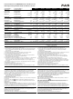
Technical Data
1)
Technische Daten
1)
CD5.121 CD5.241 CD5.241-L1 CD5.241-S1 CD5.242 CD5.243
Output Voltage Ausgangsspannung nom. 12 - 15V 24 - 28V 24V 24 - 28V 24 - 28V 24 - 28V
Factory Setting Werkseinstellung typ. 12.0V 24.1V 24.1V 24.1V 24.1V 24.1V
Output Current Ausgangsstrom nom. 8.0 - 6.4A 5.0 - 4.3A 3.8A 5.0 - 4.3A 5.0 - 4.3A 4.0 - 3.4A
PowerBoost 9.6 - 7.7A
2)
6.0 - 5.1A
2)
- 6.0 - 5.1A
2)
6.0 - 5.1A
2)
4.8 - 4.1A
2)
Output Power Ausgangsleistung nom. 96W 120W 92W 120W 120W 96W
PowerBoost 116W
2)
144W
2)
- 144W
2)
144W
2)
116W
2)
Output Ripple
3)
Ausgangswelligkeit
3)
max. 75mVpp 50mVpp 50mVpp 50mVpp 50mVpp 50mVpp
Input Voltage Eingangsspannung nom. DC 24V DC 24V DC 24V DC 24V DC 48V DC 12V
Input Voltage Range Eingangsspannungsbereich 18 - 32.4Vdc
14.4 - 35Vdc
11)
18 - 32.4Vdc
14.4 - 35Vdc
11)
14.4 - 32.4Vdc
32.4 - 35Vdc
11)
18 - 32.4Vdc
14.4 - 35Vdc
11)
36 - 60Vdc 8.4 - 16.2Vdc
8.4 - 9Vdc
11)
Input Current
4)
Eingangsstrom
4)
typ. 5.6A 7A 5.5A 7A 3.5A 12A
Voltage Input to Earth Spannung Eingang zu Erde max. 60Vdc, 42.4Vac 60Vdc, 42.4Vac 60Vdc, 42.4Vac 60Vdc, 42.4Vac 60Vdc, 42.4Vac 60Vdc, 42.4Vac
Efficiency
5)
Wirkungsgrad
5)
typ. 88.2% 90.3% 90.5% 90.3% 90.3% 87.7%
Power Losses
5)
Verlustleistung
5)
typ. 12.8W 12.9W 9.7W 12.9W 12.9W 13.5W
Operational Temp. Range Betriebstemperaturbereich -25°C to +70°C -25°C to +70°C -25°C to +70°C -25°C to +70°C -25°C to +70°C -25°C to +70°C
Output Derating Leistungsrücknahme +60 - +70°C 2.5W/°C 3W/°C 0W/°C 3W/°C 3W/°C 2.5W/°C
Storage Temp. Range Lagertemperaturbereich -40°C to +85°C -40°C to +85°C -40°C to +85°C -40°C to +85°C -40°C to +85°C -40°C to +85°C
Humidity
6)
Feuchte
6)
IEC 60068-2-30 5 - 95% r.H. 5 - 95% r.H. 5 - 95% r.H. 5 - 95% r.H. 5 - 95% r.H. 5 – 95% r.H.
Vibration
14)
Schwingen
14)
IEC 60068-2-6 2g 2g 2g 2g 2g 2g
Shock
14)
Schocken
14)
IEC 60068-2-27 30g 6ms
20g 11ms
30g 6ms
20g 11ms
30g 6ms
20g 11ms
30g 6ms
20g 11ms
30g 6ms
20g 11ms
30g 6ms
20g 11ms
Degree of Pollution Verschmutzungsgrad EN 501782222 22
Degree of Protection Schutzart EN 60529 IP20 IP20 IP20 IP20 IP20 IP20
Class of Protection Schutzklasse IEC 61140 III
7)
III
7)
III
7)
III
7)
III
7)
III
7)
Reverse Polarity Protection Verpolschutz Yes / ja
13)
Yes / ja
13)
Yes / ja
13)
Yes / ja
13)
Yes / ja
13)
Yes / ja
13)
Over-temperature Protect. Übertemperaturschutz OTP Yes / ja
8)
Yes / ja
8)
Yes / ja
8)
Yes / ja
8)
Yes / ja
8)
Yes / ja
8)
Output Over-voltage Prot. Überspannungsschutz Ausgang max. 16.8Vdc
8)
32Vdc
8)
32Vdc
8)
32Vdc
8)
32Vdc
8)
32Vdc
8)
Parallel Use
9)
Parallelschaltbar
9)
Yes / ja Yes / ja No / nein Yes / ja Yes / ja Yes / ja
Serial Use
10)
Serienschaltbar
10)
Yes / ja Yes / ja No / nein Yes / ja Yes / ja Yes / ja
Dimensions
12)
(wxhxd) Abmessungen
12)
(BxHxT) nom. 32x124x102mm 32x124x102mm 32x124x102mm 32x124x102mm 32x124x102mm 32x124x102mm
Weight Gewicht max. 425g 425g 425g 450g 425g 435g
Specialty Besonderheit - - NEC Class 2,
Spring-clamp
terminals
DC-OK Signal,
Input-low Signal
Spring-clamp term.
--
1) All parameters are specified at nominal input voltage, nominal output current, 25°C ambient
and after a 5 minutes run-in time unless otherwise noted.
2) The PowerBoost is continuously allowed up to an ambient of 45°C. Above that temperature,
do not use the PowerBoost longer than a duty cycle of 10% and not longer than 1 minute
every 10 minutes.
3) 50 Ohm measurement, bandwidth 20MHz
4) At nominal load and the lower end of the input voltage of 12V, 24Vdc or 48Vdc.
5) At nominal load and nominal input voltage of 12Vdc, 24Vdc or 48Vdc.
6) Do not energize while condensation is present.
7) PE (Ground) connection not required. However, connecting the chassis ground terminal
(Functional Earth) can be beneficial to gain a high EMI immunity.
8) Output shut-down with automatic restart.
9) Several DC/DC converter can be paralleled to increase the output power or to built redundant
systems. A fuse (or diode) on the output is only required if more than three units are
connected in parallel. Ensure that the ambient temperature of the power supply does not
exceed 45°C.
10) Use only DC/DC converters of the same type. The total output voltage should not exceed 150Vdc.
11) With derating, see datasheet
12) Depth without DIN-rail. Dimensions without plug connectors
13) Unit does not start when input voltage is reversed
14) Valid for DIN Rails according EN 60715 with a height of 15mm and a thickness of 1.3mm.
1) Alle Werte gelten bei nominaler Eingangsspannung, Nennausgangsstrom, 25°C Umgebung
und nach einer Aufwärmzeit von 5 Minuten, wenn nichts anderes angegeben ist.
2) Der PowerBoost kann <45°C dauerhaft entnommen werden. Über 45°C ist eine max.
Einschaltdauer von 10% erlaubt. Diese darf nicht öfters als 1 Minute alle 10 Minuten
wiederholt werden.
3) 50 Ohm Messung, Bandbreite 20MHz
4) Bei Nominallast und dem unteren Ende der Eingangsspannung von 12Vdc, 24Vdc od. 48Vdc
5) Bei Nominallast und Nenneingangsspannung von 12Vdc, 24Vdc oder 48Vdc
6) Nicht betreiben, solange das Gerät Kondensation aufweist.
7) PE (Erde) Verbindung ist nicht erforderlich. Ein Anschluss der Funktionserde (Chassis
ground) an einen Erd- oder Masseanschluss wird empfohlen um eine bestmögliche EMV
Störfestigkeit zu erlangen.
8) Ausgang schaltet ab und macht regelmäßig automatische Startversuche.
9) Geräte können zur Leistungserhöhung oder zum Aufbau redundanter Systeme parallel
geschaltet werden. Bei mehr als 3 Geräten sind die Ausgänge mit Dioden oder Sicherungen
zu entkoppeln. Ein Parallelbetrieb ist bis zu einer Umgebungstemperatur von 45°C möglich.
10) Nur gleiche Geräte und bis zu einer Gesamtspannung von 150Vdc
11) Mit Leistungsrücknahme, siehe Datenblatt
12) Tiefe ohne DIN-Schiene. Abmessungen ohne Steckverbinder
13) Gerät schaltet bei verpolter Eingangsspannung nicht ein.
14) Gültig für DIN-Schienen nach EN 60715 mit einer Höhe von 15mm und Stärke von 1,3mm.
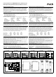
Installation
Use DIN-rails according to EN 60715 or EN 50022 with a height of 7.5 or 15mm. Mounting
orientation must be output terminals on top and input terminals on the bottom. For other
orientations see datasheet. Do not obstruct air flow as the unit is convection cooled. Ventilation
grid must be kept free of any obstructions. The following installation clearances must be kept
when power supplies are permanently fully loaded:
Left / right: 5mm (15mm in case the adjacent device is a heat source)
40mm on top, 20mm on the bottom of the unit.
Use in hazardous location areas
Units which are marked with "Class I Div 2" are suitable for use in Class I Division 2 Groups A, B,
C, D locations.
Units which are marked with II 3G Ex nA nC IIC T4 Gc are suitable for use in Group II
Category 3 (Zone 2) environments and are evaluated according to EN 60079-0:2012 and EN
60079-15:2010.
WARNING EXPLOSION HAZARDS!
Substitution of components may impair suitability for this environment. Do not disconnect the unit
or operate the voltage adjustment unless power has been switched off or the area is known to be
non-hazardous. A suitable enclosure must be provided for the end product which has a minimum
protection of IP54 and fulfils the requirements of the EN 60079-15:2010.
Installation
Geeignet für DIN-Schienen entsprechend EN 60715 oder EN 50022 mit einer Höhe von 7,5 oder
15mm. Der Einbau hat so zu erfolgen, dass sich die Eingangsklemmen unten und die
A
usgangsklemmen oben befinden. Für andere Einbaulagen siehe Datenblatt. Luftzirkulation nicht
behindern! Das Gerät ist für Konvektionskühlung ausgelegt. Es ist für ungehinderte Luftzirkulation
zu sorgen. Folgende Einbauabstände sind bei dauerhafter Volllast einzuhalten:
Links / rechts: 5mm (15mm bei benachbarten Wärmequellen)
Oben: 40mm, unten 20mm vom Gerät.
Betrieb in explosionsgefährdeter Umgebung
Geräte, die mit "Class I Div 2" gekennzeichnet sind, sind für den Einsatz in Klasse I Division 2
Gruppen A,B,C,D Umgebung geeignet.
Geräte, welche die Kennzeichnung II 3G Ex nA nC IIC T4 Gc tragen, sind nach EN 60079-
0:2012 und EN 60079-15:2010 getestet und können in Gruppe II, Kategorie 3 (Zone 2)
Umgebungen verwendet werden.
A
CHTUNG EXPLOSIONSGEFAHR!
Veränderungen am Gerät können die Tauglichkeit für diese Umgebung beeinträchtigen.
A
nschlüsse nicht abklemmen und Spannungseinstellung nicht verändern, solange Spannung
anliegt oder die Umgebung als explosionsgefährlich gilt. Das Gerät muss mindestens in ein IP54
Gehäuse, welches den Anforderungen der EN 60079-15:2010 entspricht, eingebaut werden.
CE Marking
CE mark is in conformance with EMC directive 2004/108/EC, the low-voltage directive (LVD)
2006/95/EC and the RoHS directive 2011/65/EU.
EMC Immunity: EN 61000-6-1, EN 61000-6-2
EMC Emission: EN 61000-6-3, EN 61000-6-4, FCC Part 15 Class B
CE Kennzeichnung
Das CE Zeichen ist angebracht und erklärt die Erfüllung der EMV Richtlinie 2004/108/EG, der
Niederspannungsrichtlinie 2006/95/EG und der RoHS Richtlinie 2011/65/EU.
Störfestigkeit: EN 61000-6-1, EN 61000-6-2
Störaussendung: EN 61000-6-3, EN 61000-6-4, FCC Part 15 Klasse B