
Owner manual

Instruction Manual for the DIMENSION CD-Series DC/DC Converter
Bedienungsanleitung für DC/DC Wandler der Dimension CD-Serie
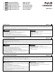
Input Fuses and Input Protection
A
ll units have an input fuse included (device protection, not externally accessible). The units are
tested and approved for branch circuits up to 50A. An external protection is only required if the
supplying branch has an ampacity greater than this. In some countries local regulations might
apply. Also check local codes and requirements. If an external fuse is necessary or utilized,
minimum requirements need to be considered. To avoid nuisance tripping of the circuit breaker,
use a minimum value of 10A B-Characteristic or 8A C-Characteristic. (Minimum 16A B- or C-
Characteristic for the CD5.243)
Eingangssicherungen und Eingangsabsicherung
A
lle Geräte haben eine Sicherung eingebaut (Gerätesicherung, nicht austauschbar durch
A
nwender). Die Geräte sind geprüft und zugelassen zum Anschluss an Stromkreisen bis max.
50A. Ein zusätzlicher externer Schutz ist nur erforderlich wenn der Speisestromkreis mit einem
höheren Wert abgesichert ist oder wenn nationale Richtlinien es vorschreiben. Falls ein externes
Schutzelement verwendet wird, soll dieses nicht kleiner als 10A B- Charakteristik oder 8A C-
Charakteristik sein um ein fehlerhaftes Auslösen zu vermeiden. (Beim CD5.243 mindestens 16A
B- oder C-Charakteristik)
Terminals and Wiring
Use appropriate copper cables that are designed for a minimum operating temperature of:
60°C for ambient temperatures up to 45°C,
75°C for ambient temperatures up to 60°C and
90°C for ambient temperatures up to 70°C.
Follow national installation codes and regulations! Ensure that all strands of a stranded wire enter
the terminal connection! Ferrules are allowed.
Screw terminals Spring-clamp term. Signals
Solid wire 0.5-6mm
2
0.5-6mm
2
0.2-1.5mm
2
Stranded wire 0.5-4mm
2
0.5-4mm
2
0.2-1.5mm
2n
American wire gauge 20-10 AWG 20-10 AWG 22-14 AWG
Wire stripping length 7mm / 0.28inch 10mm / 0.4inch 6mm / 0.25inch
Tightening torque 0.8Nm / 7lb.inch - 0.4Nm / 3.5lb.inch
Anschlussklemmen und Verdrahtung
Verwenden Sie geeignete Kupferkabel, die mindestens für:
60°C bei einer Umgebungstemperatur bis zu 45°C,
75°C bei einer Umgebungstemperatur bis zu 60°C und
90°C bei einer Umgebungstemperatur bis zu 70°C zugelassen sind.
Beachten Sie nationale Bestimmungen und Installationsvorschriften! Stellen Sie sicher, dass
keine einzelnen Drähte von Litzen abstehen. Aderendhülsen sind erlaubt.
Schraubklemmen Federkraftklemmen Signale
Starrdraht 0,5-6mm
2
0,5-6mm
2
0,2-1.5mm
2
Litze 0,5-4mm
2
0,5-4mm
2
0,2-1.5mm
2
AWG 20-10 AWG 20-10 AWG 22-14 AWG
Abisolierlänge 7mm / 0,28inch 10mm / 0,4inch 6mm / 0,25inch
Anzugsdrehmoment 0,8Nm / 7lb.inch - 0,4Nm / 3.5lb.inch
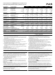
Output- and Overload Characteristic
The units are overload, no-load, short-circuit proof. The unit has a power reserve of 20%.included
(except CD5.241-L1). This extra current may even be used continuously at temperatures up to
+45°C. At overload, the output current flows continuously. The unit does not switch-off or hiccup at
overload. Typical characteristic curves can be found in the figures 1 to 5.
Ausgangs- und Überlastverhalten
Die Geräte sind leerlauf-, überlast- und kurzschlussfest. Die Geräte verfügen über 20%
Reserveleistung (außer CD5.241-L1), die bis zu einer Umgebungstemperatur von 45°C dauerhaft
entnommen werden kann. Bei Überlast fließt kontinuierlich Strom. Das Gerät schaltet nicht ab und
hat auch keinen „Hiccup“ Modus. Das typische Verhalten ist in Bildern 1 bis 5 gezeigt.
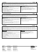
Dielectric Strength (see Fig. 6)
The output voltage is floating and separated from the input according to SELV (IEC/EN 60950-1)
and PELV (EN 60204-1, EN 50178; IEC 62103, IEC 60364-4-41) requirements. Type and factory
tests are conducted by the manufacturer. Field tests may be conducted in the field using the
appropriate test equipment which applies the voltage with a slow ramp (2s up and 2s down).
Connect all input poles as well as all output poles together before conducting the test. When
testing, set the cut-off current settings to the value in the table below.
A B C D
Type Test (60s) 1500Vac 1500Vac*) 500Vac 500Vac
Factory Test (5s) 1500Vac 1500Vac*) 500Vac 500Vac
Field Test (5s) 1000Vac 1000Vac 500Vac 500Vac
Cut-off current setting >30mA >30mA >12mA >1mA
*) only 1000Vac for the CD5.241-S1
Isolationsfestigkeit (siehe Bild 6)
Die Ausgangsspannung hat keinen Bezug zur Erde oder Schutzleiter und ist zum Eingang nach
den SELV (IEC/EN 60950-1) und PELV (EN 60204-1, EN 50178, IEC 62103, IEC 60364-4-41)
Standards getrennt. Typ- und Stückprüfungen werden beim Hersteller durchgeführt. Wieder-
holungsprüfungen dürfen mittels geeigneten Prüfgenerators mit langsam (2s) ansteigenden und
abfallenden Spannungsrampen in der Anwendung erfolgen. Vor den Tests sind alle Eingangs- wie
auch alle Ausgangspole miteinander zu verbinden. Während der Tests darf die Strom-
A
bschaltschwelle nicht kleiner als der in der Liste angegebene Wert sein.
A B C D
Typprüfung (60s) 1500Vac 1500Vac*) 500Vac 500Vac
Stückprüfung (5s) 1500Vac 1500Vac*) 500Vac 500Vac
Wiederholungsprüfung (5s) 1000Vac 1000Vac 500Vac 500Vac
Strom- Abschaltschwelle >30mA >30mA >12mA >1mA
*) nur 1000Vac für das CD5.241-S1
DC-OK Relay Contact (only for CD5.241-S1)
This feature monitors the output voltage, which is produced by the power supply, and is
independent of a return voltage from a unit which is connected in parallel. The green DC-OK LED
and the DC-OK relay contact operate synchronized.
Contact closes when the output voltage reaches the adjusted value after turn-on of the power
supply or when the output voltage reaches 90% after a dip in the output.
Contact opens when the output voltage dips more than 10%. Short dips will be extended to a
length of 250ms. Dips shorter than 1ms will be ignored.
Contact ratings: max.: 60Vdc 0.3A, 30Vdc 1A, 30Vac 0.5A, resistive load, min. current 1mA
DC-OK Relais Kontakt (nur für CD5.241-S1)
Diese Funktion überwacht die vom Gerät erzeugte Ausgangsspannung und lässt sich von einer
rückwärts eingespeisten Spannung nicht beeinflussen (z.B.: bei Parallelschaltung). Die grüne
„DC-OK“ LED und der „DC-OK“ Relaiskontakt arbeiten synchron.
Kontakt schließt sobald nach dem Einschalten der Ausgang den eingestellten Wert erreicht oder
wenn nach Einbruch des Ausgangs die Spannung wieder >90% des eingestellten Wertes wird.
Kontakt öffnet sobald der Ausgang um mehr als 10% einbricht. Kurze Einbrüche werden auf
250ms verlängert. Einbrüche kürzer 1ms werden ignoriert.
Kontakt Belastbarkeit: max.: 60Vdc 0.3A, 30Vdc 1A, 30Vac 0.5A, (R-Last), min. Strom 1mA
Input-Low Relay Contact (only for CD5.241-S1)
This feature monitors the input voltage of the DC/DC converter. It is a “Normally Closed” contact.
The yellow Input-Low LED and the Input-Low relay contact operate synchronized.
Contact is closed: When the input voltage falls below 19.5Vdc (typ.)
Contact is open: As soon as the input voltage reaches 20.5Vdc (typ.)
Contact ratings: Max.: 60Vdc 0.3A, 30Vdc 1A, 30Vac 0.5A, resistive load, min.: 1mA
Input-Low Relais Kontakt (nur für CD5.241-S1)
Diese Funktion überwacht den Eingang und ist als “Normally Closed” Kontakt ausgeführt. Die
gelbe „Input-Low“ LED und der „Input-Low“ Relaiskontakt arbeiten synchron.
Kontakt ist geschlossen: Wenn die Eingangsspannung kleiner 19.5Vdc (typ.) ist.
Kontakt ist geöffnet: Sobald die Eingangsspannung 20.5Vdc (typ.) überschreitet.
Belastbarkeit: Max.: 60Vdc 0.3A, 30Vdc 1A, 30Vac 0.5A, (R-Last), min.: 1mA
Fig. 1 / Bild 1
CD5.241; CD5.241-S1
Fig. 2 / Bild 2
CD5.242
Fig. 3 / Bild 3
CD5.121
Fig. 4 / Bild 4
CD5.243
Fig. 5 / Bild 5
CD5.241-L1
Fig. 6 / Bild 6
Insulation / Isolation
Out put Volt age
0
048
4
8
12
28V
16
20
24
12
A
1062
Adjustment
Ra n g e
Out put Current
Out put Voltage
0
048
4
8
12
28V
16
20
24
12
A
1062
Adjustment
Range
Output Current
Out put Volt age
0
068
3
6
9
18V
12
15
18
A
16102 4 12 14
Adjustment
Ra n g e
Out put Current
Output Voltage
0
048
4
8
12
28V
16
20
24
12
A
1062
Adjustment
Range
Output
Current
Output Voltage
0
024
4
8
12
28V
16
20
24
6
A
31 5
Output Current
A
D
C
B
B
+
Input Signals
Chassis
ground
Output
-
+
-
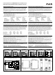
Fig. 7 / Bild 7
Functional Diagram / Funktionsschaltbild
Fig. 8 / Bild 8 Dimensions / Abmessungen
CD5.121/241/242/243/241-L1 CD5.241-S1 CD5.121/241/242/243 CD5.241-L1 CD5.241-S1
+
+
-
-
V
OUT
Input Fuse
&
Input Filter
Output
Voltage
Regulator
Power
Converter
Output
Filter
DC
ok
Output
Over-
Voltage
Protection
Reverse
Polarity
Protection
&
Inrush
Limiter
Chassis
Ground
+
-
Over-
Temperature
Protection
DC-ok
Relay
Output
Voltage
Monitor
13
14
Input
low
Relay
11
12
Input
Voltage
Monitor
Input
low
*) not for CD5.241-L1
*)
only for CD5.241-S1
PU-375.011.00-10C