
Datasheet


CPS20.121
C-Series
12V, 30A, SINGLE PHASE INPUT
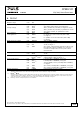
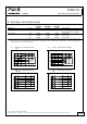
10. LIFETIME EXPECTANCY AND MTBF
AC 100V AC 120V AC 230V
Lifetime expectancy
*)
168 000h
*)
170 000h
*)
174 000h
*)
at 12V, 15A and 40°C
475 000h
*)
481 000h
*)
492 000h
*)
at 12V, 15A and 25°C
50 000h 50 000h 54 000h at 12V, 30A and 40°C
141 000h
*)
141 000h
*)
153 000h
*)
at 12V, 30A and 25°C
MTBF
**) SN 29500, IEC 61709 413 000h 428 000h 554 000h at 12V, 30A and 40°C
702 000h 728 000h 776 000h at 12V, 30A and 25°C
MTBF
**) MIL HDBK 217F 253 000h 259 000h 278 000h at 12V, 30A and 40°C;
Ground Benign GB40
353 000h 358 000h 380 000h at 12V, 30A and 25°C;
Ground Benign GB25
61 000h 62 000h 68 000h at 12V, 30A and 40°C;
Ground Fixed GF40
82 000h 83 000h 91 000h at 12V, 30A and 25°C;
Ground Fixed GF25
*) The Lifetime expectancy shown in the table indicates the minimum operating hours (service life) and is determined by the lifetime
expectancy of the built-in electrolytic capacitors. Lifetime expectancy is specified in operational hours and is calculated according to the
capacitor’s manufacturer specification. The manufacturer of the electrolytic capacitors only guarantees a maximum life of up to 15 years
(131 400h). Any number exceeding this value is a calculated theoretical lifetime which can be used to compare devices.
**) MTBF stands for Mean Time Between Failure, which is calculated according to statistical device failures, and indicates reliability of a
device. It is the statistical representation of the likelihood of a unit to fail and does not necessarily represent the life of a product.
The MTBF figure is a statistical representation of the likelihood of a device to fail. A MTBF figure of e.g. 1 000 000h means that
statistically one unit will fail every 100 hours if 10 000 units are installed in the field. However, it can not be determined if the failed unit
has been running for 50 000h or only for 100h.
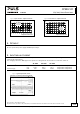
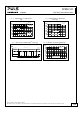
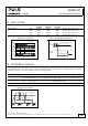
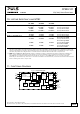
11. FUNCTIONAL DIAGRAM
Fig. 11-1 Functional diagram
+
+
-
-
Output
Over-
Voltage
Protection
PFC
Converter
Output
Voltage
Regulator
Power
Converter
Output
Filter
Output
Voltage
Monitor
Output
Power
Manager
Temper-
ature
Shut-
down
Input Fuse
Input Filter
Input Rectifier
Active Inrush Limiter
V
OUT
L
N
DC-ok
Contact
DC-ok
LED
Single /
Parallel
DC-ok
Relay
Apr. 2014 / Rev. 1.4 DS-CPS20.121-EN
All parameters are specified at 12V, 30A, 230Vac, 25°C ambient and after a 5 minutes run-in time unless otherwise noted.
www.pulspower.com Phone +49 89 9278 0 Germany
10/26