
Manual


CPS20 Instruction Manual for Power Supplies
CPS20 Bedienungsanleitung für Stromversorgungen
Installation
Use DIN-rails according to EN 60715 with a height of 7.5 or 15mm. Mounting orientation must be
output and input terminals on the bottom. For other orientations see datasheet. Do not obstruct air
flow as the unit is convection cooled. Ventilation grid must be kept free of any obstructions. The
following installation clearances must be kept when power supplies are permanently fully loaded:
Left / right: 5mm (15mm in case the adjacent device is a heat source)
40mm on top, 20mm on the bottom of the unit.
The unit can be used at altitudes up to 6000m. For restrictions and details see datasheets.
However, agency approvals apply only for altitudes up to 2000m.
A disconnecting means shall be provided for the output of the power supplies when used in
applications according to CSA C22.2 No 107.1-01.
Use in hazardous location areas
Units which are marked with "Class I Div 2" are suitable for use in Class I Division 2 Groups A, B,
C, D locations.
Units which are marked with II 3G Ex nA nC IIC T3 Gc are suitable for use in Group II
Category 3 (Zone 2) environments and are evaluated according to EN 60079-0:2012 and EN
60079-15:2010.
WARNING EXPLOSION HAZARDS!
Substitution of components may impair suitability for this environment. Do not disconnect the unit
or operate the voltage adjustment unless power has been switched off or the area is known to be
non-hazardous. A suitable enclosure must be provided for the end product which has a minimum
protection of IP54 and fulfils the requirements of the EN 60079-15:2010.
2) Altitude is higher than 2000m.
Installation
Geeignet für DIN-Schienen entsprechend EN 60715 mit einer Höhe von 7,5 oder 15mm. Der
Einbau hat so zu erfolgen, dass sich die Eingangs- und Ausgangsklemmen unten befinden. Für
andere Einbaulagen siehe Datenblatt. Luftzirkulation nicht behindern! Das Gerät ist für
Konvektionskühlung ausgelegt. Es ist für ungehinderte Luftzirkulation zu sorgen. Folgende
Einbauabstände sind bei dauerhafter Volllast einzuhalten:
Links / rechts: 5mm (15mm bei benachbarten Wärmequellen)
Oben: 40mm, unten 20mm vom Gerät.
Das Gerät ist für Aufstellhöhen bis 6000m geeignet. Notwendige Einschränkungen und Hinweise
für Anwendungen über 2000m befinden sich in den Datenblättern. Die Gerätezulassungen sind
nur bis 2000m gültig.
Bei Anwendungen nach CSA C22.2 No 107.1-01 muss der Ausgang mit einer Trennvorrichtung
versehen werden.
Betrieb in explosionsgefährdeter Umgebung
Geräte, die mit "Class I Div 2" gekennzeichnet sind, sind für den Einsatz in Klasse I Division 2
Gruppen A,B,C,D Umgebung geeignet.
Geräte, die mit II 3G Ex nA nC IIC T3 Gc, gekennzeichnet sind, sind nach EN 60079-0:2012
und EN 60079-15:2010 getestet und kann in Gruppe II, Kategorie 3 (Zone 2) Umgebungen
verwendet werden.
ACHTUNG EXPLOSIONSGEFAHR!
Veränderungen am Gerät können die Tauglichkeit für diese Umgebung beeinträchtigen.
Anschlüsse nicht abklemmen und Spannungseinstellung nicht verändern, solange Spannung
anliegt oder die Umgebung als explosionsgefährlich gilt. Das Gerät muss mindestens in ein IP54
Gehäuse, welches den Anforderungen der EN 60079-15:2010 entspricht, eingebaut werden.
CE Marking
CE mark is in conformance with EMC directive 2004/108/EC, the low-voltage directive (LVD)
2006/95/EC and the RoHS directive 2011/65/EU.
EMC Immunity: EN 61000-6-1, EN 61000-6-2
EMC Emission: EN 61000-6-3, EN 61000-6-4, FCC Part 15 Class B
CE Kennzeichnung
Das CE Zeichen ist angebracht und erklärt die Erfüllung der EMV Richtlinie 2004/108/EG, der
Niederspannungsrichtlinie 2006/95/EG und der RoHS Richtlinie 2011/65/EU.
Störfestigkeit: EN 61000-6-1, EN 61000-6-2
Störaussendung: EN 61000-6-3, EN 61000-6-4, FCC Part 15 Klasse B
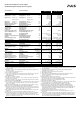
Input Fuses
Internal input fuse included, not user accessible. The unit is tested and approved for branch
circuits up to 30A (UL) 32A (IEC). An external protection is only required if the supplying branch
has an ampacity greater than this, however, in some countries local regulations might apply.
Check local codes and requirements. If an external fuse is necessary or utilized, minimum
requirements need to be considered to avoid nuisance tripping of the circuit breaker. Use a
minimum value of 10A B- or C-Characteristic breaker.
Sicherungen am Eingang
Das Gerät besitzt eine eingebaute Eingangssicherung, die nicht anwenderzugänglich ist. Das
Gerät ist geprüft und zugelassen zum Anschluss an Stromkreisen bis max. 30A (UL) 32A (IEC).
Ein zusätzlicher externer Schutz ist nur erforderlich, wenn der Speisestromkreis mit einem
höheren Wert abgesichert ist oder nationale Richtlinien es vorschreiben. Um ein fehlerhaftes
Auslösen externer Schutzelemente zu vermeiden sollen diese den Minimalwert von 10A B- oder
C-Charakteristik nicht unterschreiten:
Terminals and Wiring
Use appropriate copper cables that are designed for a minimum operating temperature of:
60°C for ambient temperatures up to 45°C,
75°C for ambient temperatures up to 60°C and
90°C for ambient temperatures up to 70°C.
Follow national installation codes and regulations! Ensure that all strands of a stranded wire enter
the terminal connection! Ferrules are allowed. Unused terminal must be closed.
Input / Output Signals
Solid wire 0.5-6mm
2
0.15-1.5mm
2
Stranded wire 0.5-4mm
2
0.15-1.5mm
2n
American wire gauge AWG 20-10 AWG 26-14
Max. wire diameter (including ferrules) 2.8mm 1.5mm
Wire stripping length 7mm / 0.28inch 7mm / 0.28inch
Tightening torque 1Nm / 9lb.inch Spring-clamp terminal
Anschlussklemmen und Verdrahtung
Verwenden Sie geeignete Kupferkabel, die mindestens für:
60°C bei einer Umgebungstemperatur bis zu 45°C,
75°C bei einer Umgebungstemperatur bis zu 60°C und
90°C bei einer Umgebungstemperatur bis zu 70°C zugelassen sind.
Aderendhülsen sind erlaubt. Nationale Bestimmungen und Installationsvorschriften beachten!
Achten, dass keine einzelnen Drähte von Litzen abstehen. Nichtbenutzte Klemmen schließen.
Eingang / Ausgang Signale
Starrdraht 0,5-6mm
2
0,15-1,5mm
2
Litze 0,5-4mm
2
0,15-1,5mm
2
AWG AWG 20-10 AWG 26-14
Max. Drahtdurchmesser (inkl. Aderendhülsen) 2,8mm 1,5mm
Abisolierlänge 7mm / 0,28inch 7mm / 0,28inch
Anzugsdrehmoment 1Nm / 9lb.inch Federkraftklemme
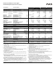
Isolation and Dielectric Strength (see Fig. 5)
The output voltage is floating and separated from the input according to SELV (IEC/EN 60950-1)
and PELV (EN 60204-1, EN 50178; IEC 62103, IEC 60364-4-41) requirements. Type and factory
tests are conducted by the manufacturer. Field tests may be conducted in the field using the
appropriate test equipment which applies the voltage with a slow ramp (2s up and 2s down).
Connect all phase-terminals together as well as all output poles before the test is conducted.
When testing, set the cut-off current settings to the value in the table below.
A B C D
Type Test (60s) 2500Vac 3000Vac 1000Vac 500Vac
Factory Test (5s) 2500Vac 2500Vac 500Vac 500Vac
Field Test (5s) 2000Vac 2000Vac 500Vac 500Vac
Cut-off current setting >15mA >15mA >20mA >1mA
Galvanische Trennung und Isolationsfestigkeit (siehe Bild 5)
Die Ausgangsspannung hat keinen Bezug zur Erde oder Schutzleiter und ist zum Eingang nach
den SELV (IEC/EN 60950-1) und PELV (EN 60204-1, EN 50178, IEC 62103, IEC 60364-4-41)
Standards getrennt. Typ- und Stückprüfungen werden beim Hersteller durchgeführt. Wieder-
holungsprüfungen dürfen mittels geeigneten Prüfgenerators mit langsam (2s) ansteigenden und
abfallenden Spannungsrampen in der Anwendung erfolgen. Vor den Tests sind alle Phasen wie
auch alle Ausgangspole miteinander zu verbinden. Während der Tests darf die Strom-
Abschaltschwelle nicht kleiner als der in der Liste angegebene Wert sein.
A B C D
Typprüfung (60s) 2500Vac 3000Vac 1000Vac 500Vac
Stückprüfung (5s) 2500Vac 2500Vac 500Vac 500Vac
Wiederholungsprüfung (5s) 2000Vac 2000Vac 500Vac 500Vac
Strom- Abschaltschwelle >15mA >15mA >20mA >1mA
Hiccup
PLUS
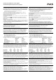
Overload Characteristic (see figures 3 and 4)
The units are overload, no-load, short-circuit proof. The output current is electronically controlled.
During an overcurrent situation, the output voltage will be reduced after a defined time. If the
voltage falls below 6V for the 12V unit, 13V for the 24V units, 20V for the 36V unit and 25V for the
48V units, the unit switches to the Hiccup
PLUS
mode. In this mode, the output switches off followed
by a restart attempt after 18s for 2s. This cycle is repeated as long as the overload or short circuit
exists. If the overload or short circuit has been cleared, the device will operate normally.
Hiccup
PLUS
Überlastverhalten (siehe Bilder 3 und 4)
Die Geräte sind leerlauf-, überlast- und kurzschlussfest. Der Ausgangsstrom ist elektronisch
überwacht. Während einer Überstromsituation wird nach einer bestimmten Zeit die
Ausgangsspannung reduziert. Fällt die Spannung unter 6V beim 12V Gerät, 13V bei 24V Geräten,
20V beim 36V Gerät oder 25V bei 48V Geräten schaltet das Gerät in den Hiccup
PLUS
Modus. In
diesen Modus schaltet das Gerät ab und macht nach 18s einen Startversuch mit einer Dauer von
2s. Der Vorgang wiederholt sich solange, bis die Überlast oder der Kurzschluss entfernt ist. Nach
entfernen der Überlast oder des Kurzschlusses schaltet das Gerät wieder in den Normalbetrieb.
Single Use / Parallel Use Selector
This selector on the front of the unit enables a load sharing when power supplies are connected in
parallel. The “Parallel Use” mode regulates the output voltage in such a manner that the voltage at
no load is approx. 4% higher than at nominal load.
If no jumper is plugged in, the unit is also in “Single Use”. Factory setting is “Single Use”.
Instructions for parallel use:
The output voltage shall be adjusted to the same value (±100mV) in “Single Use” at the same load
condition on all units, or shall be left with the factory settings. Afterwards, the jumper on the front
of the unit shall be moved from “Single Use” to “Parallel Use”
„Single Use“ / „Parallel Use“ Steckbrücke
Diese Steckbrücke an der Frontseite des Geräts ermöglicht eine Lastaufteilung, wenn mehrere
Geräte parallel geschaltet sind. In „Parallel Use“ Modus ist die Ausgangsspannung so geregelt,
dass diese im Leerlauf um etwa 4% höher ist als bei Nennlast.
Ein nicht eingesteckter Jumper bedeutet auch „Single Use“. Werkseinstellung ist „Single Use“.
Anleitung für Parallelbetrieb:
Die Ausgangsspannung aller Geräte bei gleicher Belastung in „Single Use“ auf ±100mV genau
einstellen oder in Werkseinstellung belassen. Danach die Steckbrücke an der Front des Gerätes
von „Single Use“ auf „Parallel Use“ umstecken.
DC-OK Relay Contact (see Fig. 6)
This feature monitors the output voltage, which is produced by the power supply, and is
independent of a return voltage from a unit which is connected in parallel.
Contact closes when the output voltage is above 90% of the adjusted value.
Contact opens when the output voltage is typ. below 90% of the adjusted value. Short dips will
be extended to a length of 250ms. Dips shorter than 1ms will be ignored.
Contact ratings: max.: 60Vdc 0.3A, 30Vdc 1A, 30Vac 0.5A, resistive load, min. current 1mA
DC-OK Relais Kontakt (siehe Bild 6)
Diese Funktion überwacht die vom Gerät erzeugte Ausgangsspannung und lässt sich von einer
rückwärts eingespeisten Spannung nicht beeinflussen (z.B.: bei Parallelschaltung)
Kontakt schließt, wenn die Ausgangsspannung typ. höher als 90% des eingestellten Wertes ist.
Kontakt öffnet, wenn die Ausgangsspannung typ. kleiner als 90% des eingestellten Wertes ist.
Kurze Einbrüche werden auf 250ms verlängert. Einbrüche kürzer 1ms werden ignoriert.
Kontakt Belastbarkeit: max.: 60Vdc 0.3A, 30Vdc 1A, 30Vac 0.5A, (R-Last), min. Strom 1mA