
User Manual

CS20 Series: Power Supply Instruction Manual
CS20 Serie: Bedienungsanleitung für Stromversorgung
Input Fuses
The internal input fuse is not user accessible. The unit is tested and approved for branch circuits
up to 32A. An external protection is only required if the supplying branch has an ampacity greater
than this, however, in some countries local regulations might apply. Check local codes and
requirements. If an external fuse is necessary or utilized, minimum requirements need to be
considered to avoid nuisance tripping of the circuit breaker. A minimum value of 10A B- or C-
Characteristic breaker should be used.
Sicherungen am Eingang
Das Gerät besitzt eine eingebaute Eingangssicherung, die nicht anwenderzugänglich ist. Das
Gerät ist geprüft und zugelassen zum Anschluss an Stromkreisen bis max. 32A. Ein zusätzlicher
externer Schutz ist nur erforderlich, wenn der Speisestromkreis mit einem höheren Wert
abgesichert ist oder nationale Richtlinien es vorschreiben. Falls ein externes Schutzelement
verwendet wird, soll dieses nicht kleiner als 10A B- oder C-Charakteristik sein, um ein fehlerhaftes
Auslösen zu vermeiden.
EMC Electromagnetic Compatibility
These power supplies are suitable for applications in industrial environment as well as in
residential, commercial and light industry environment without any restrictions. These devices
comply with FCC Part 15 rules.
CE mark is in conformance with the EMC directive 2004/108/EC, the low-voltage directive (LVD)
2006/95/EC and the RoHS directive 2011/65/EC.
EMC Immunity: EN 61000-6-1, EN 61000-6-2
EMC Emission EN 61000-6-3, EN 61000-6-4, FCC Part 15 Class B
EMV Elektromagnetische Verträglichkeit
Diese Stromversorgungen erfüllen die Anforderungen für Anwendungen in industrieller Umgebung
und für den Wohn-, Geschäfts- und Gewerbebereich ohne Einschränkungen. Die Geräte erfüllen
auch die Anforderungen der FCC Teil 15.
Das CE Zeichen ist angebracht und erklärt die Erfüllung der EMV Richtlinie 2004/108/EG, der
Niederspannungsrichtlinie 2006/95/EG und der RoHS Richtlinie 2011/65/EG.
Störfestigkeit: EN 61000-6-1, EN 61000-6-2
Störaussendung: EN 61000-6-3, EN 61000-6-4, FCC Part 15 Klasse B
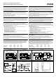
Output- and Overload Characteristic (see Fig. 1 and 2)
The power supplies are overload, no-load, short-circuit proof. The units have power reserves of
20% included. This extra current may even be used continuously at temperatures up to +45°C. At
permanent overloads, the unit shuts-off and makes periodical restart attempts (hiccup mode). In
such cases, the unit will be off for 18s followed by an on cycle of 2s with max. 576W. This cycle is
repeated as long as the overload exists.
Ausgangs- und Überlastverhalten (siehe Bilder 1 und 2)
Die Geräte sind leerlauf-, überlast- und kurzschlussfest. Die Geräte verfügen über 20%
Reserveleistung, die bis zu einer Umgebungstemperatur von 45°C auch dauerhaft entnommen
werden kann. Bei dauerhafter Überlast schaltet die Stromversorgung ab und macht periodische
Startversuche (Hiccup-mode). In solchen Fällen schaltet die Stromversorgung für 18s aus und
macht dann einen neuen Startversuch, bei dem wieder für 2s die 576W zur Verfügung stehen.
Der Vorgang wiederholt sich solange die Überlast besteht.
Terminals and Wiring
Use appropriate copper cables that are designed for minimum operating temperatures of:
60°C for ambient up to 45°C and 75°C for ambient up to 60°C and 90°C for ambient up to 70°C
minimum. Follow national installation codes and regulations! Ensure that all strands of a stranded
wire enter the terminal connection! Ferrules are allowed.
Power terminals (screw terminals):
Solid wire / Stranded wire / American wire gauge: 0.5-6mm
2
/ 0.5-4mm
2
/ AWG20-10
Max. wire diameter: 2.8mm (including ferrules)
Wire stripping length: 7mm / 0.28inch
Screw driver: 3.5mm slotted or Philips No 2
Recommended tightening torque: 1Nm / 9lb.in
DC-OK signal terminal (spring-clamp style):
Solid wire / Stranded wire / American wire gauge: 0.15-1.5mm
2
/ 0.15-1.5mm
2
/ AWG26-14
Max. wire diameter: 1.5mm (including ferrules)
Wire stripping length: 7mm / 0.28inch
Screw driver: 3.5mm slotted (to open the spring)
Anschlussklemmen und Verdrahtung
Verwenden Sie Kupferkabel, die für folgende Mindest- Betriebstemperatur zugelassen sind:
60°C bei Umgebungstemperaturen bis zu 45°C und 75°C bei Umgebungstemperaturen bis zu
60°C und 90°C bei Umgebungstemperaturen bis zu 70°C. Beachten Sie nationale Bestimmungen
und Installationsvorschriften! Stellen Sie sicher, dass keine einzelnen Drähte von Litzen abstehen.
Aderendhülsen sind erlaubt.
Leistungsanschlüsse (Schraubklemme):
Starrdraht / Litze / Amerikanischer Querschnitt: 0,5-6mm
2
/ 0,5-4mm
2
/ AWG20-10
Maximaler Drahtdurchmesser: 2,8mm (inklusive Aderendhülsen)
Abisolierlänge: 7mm / 0,28inch
Schraubendreher: Schlitzschraubendreher 3,5mm oder Philips No 2
Empfohlenes Anzugsdrehmoment: 1Nm / 9lb.in
DC-OK Signalklemmen (Federkraftklemmen):
Starrdraht / Litze / Amerikanischer Querschnitt: 0,15-1,5mm
2
/ 0,15-1,5mm
2
/ AWG26-14
Maximaler Drahtdurchmesser: 1,5mm (inklusive Aderendhülsen)
Abisolierlänge: 7mm / 0,28inch
Schraubendreher: Schlitzschraubendreher 3,5mm zum Betätigen der Feder
DC-OK Output (see Fig. 5)
CS20.241, CS20.481:
This feature monitors the output voltage, which is produced by the power supply, and is
independent of a return voltage from a unit which is connected in parallel.
The relay contact closes when the output voltage reaches 90% of the adjusted value. The contact
opens at voltages below this level. Short dips will be extended to a length of 100ms. Dips shorter
than 1ms will be ignored.
DC-OK Signalausgang (siehe Bild 5)
CS20.241, CS20.481:
Diese Funktion überwacht die vom Gerät erzeugte Ausgangsspannung und lässt sich von einer
rückwärts eingespeisten Spannung nicht beeinflussen (z.B.: bei Parallelschaltung)
Der Relaiskontakt schließt sobald 90% der eingestellten Ausgangsspannung erreicht wird. Bei
kleineren Spannungen öffnet dieser Kontakt wieder. Kurze Einbrüche werden auf 100ms
verlängert. Einbrüche kürzer 1ms werden ignoriert.
Dielectric Strength (see Fig. 4)
The output voltage is floating and separated from the input according to SELV (IEC/EN 60950-1)
and PELV (EN 60204-1, EN 50178; IEC 62103, IEC 60364-4-41) requirements. Type and factory
tests are conducted by the manufacturer. Field tests may be conducted in the field using the
appropriate test equipment which applies the voltage with a slow ramp (2s up and 2s down).
Connect all phase-terminals together as well as all output poles before the test is conducted.
When testing, set the cut-off current settings to the value in the table below.
A B C D
Type Test (60s) 2500Vac 3000Vac 500Vac 500Vac
Factory Test (5s) 2500Vac 2500Vac 500Vac 500Vac
Field Test (5s) 2000Vac 2000Vac 500Vac 500Vac
Cut-off current setting > 15mA > 15mA > 20mA > 1mA
Isolationsfestigkeit (siehe Bild 4)
Die Ausgangsspannung hat keinen galvanischen Bezug zur Erde oder Schutzleiter und ist zum
Eingang nach den SELV (IEC/EN 60950-1) und PELV (EN 60204-1, EN 50178, IEC 62103, IEC
60364-4-41) Standards getrennt. Typ- und Stückprüfungen werden beim Hersteller durchgeführt.
Wiederholungsprüfungen dürfen mittels geeigneten Prüfgenerators mit langsam (2s)
ansteigenden und abfallenden Spannungsrampen in der Anwendung erfolgen. Vor den Tests sind
alle Phasen wie auch alle Ausgangspole miteinander zu verbinden. Während der Tests darf die
Strom- Abschaltschwelle nicht kleiner als der in der Liste angegebene Wert sein.
A B C D
Typprüfung (60s) 2500Vac 3000Vac 500Vac 500Vac
Stückprüfung (5s) 2500Vac 2500Vac 500Vac 500Vac
Wiederholungsprüfung (5s) 2000Vac 2000Vac 500Vac 500Vac
Strom- Abschaltschwelle > 15mA > 15mA > 20mA > 1mA
Fig. 1 / Bild 1
Output Characteristic 24V units/
Ausgangskennlinie 24V Geräte, typ.
Fig. 2 / Bild 2
Output Characteristic 48V units/
Ausgangskennlinie 48V Geräte, typ.
Fig. 3 / Bild 3
Functional Diagram / Funktionsschaltbild
Output Voltage
(Single Use, typ.)
0
025
4
8
12
28V
16
20
24
40A155 10 20 30 35
Adjustment
Range
Output Current
Continuous
current
Factory
setting
Hiccup
mode
Output Voltage
(Single Use, typ.)
0
012.5
8
16
24
56V
32
40
48
20A7.52.5 5 10 15 17.5
Adjustment
Range
Output Current
Continuous
current
Factory
setting
Hiccup
mode
+
+
-
-
Output
Over-
Voltage
Protection
PFC
Converter
Output
Voltage
Regulator
Power
Converter
Output
Filter
Output
Voltage
Monitor
Output
Power
Manager
Temper-
ature
Shut-
down
Input Fuse
Input Filter
Input Rectifier
Active Inrush Limiter
V
OUT
L
N
DC-ok
Contact
DC-ok
LED
Single /
Parallel
DC-ok
Relay
Fig. 4 / Bild 4
Insulation / Isolation
Fig. 5 / Bild 5
DC-OK Signal
Fig. 6 / Bild 6 Dimensions / Abmessungen
AD
C
B
B
N
L
Input DC-ok
Earth, PE
Output
DC-ok
+/-
100ms
0.9* V
ADJ
<
1ms
10%
open
V
OUT
= V
ADJ
openclosed closed
>
1ms
PU-382.010.00-10A