
Datasheet


CT5.121
C-Series
12V, 8A, TWO-PHASE INPUT
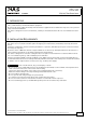
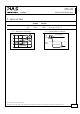
9. FUNCTIONAL DIAGRAM
Fig. 9-1 Functional diagram
+
+
-
-
V
OUT
Output
Over-
Voltage
Protection
PFC
Inductor
Inrush
Limiter
Transient
Filter
Input Fuses
Input Filter
Input
Rectifier
Output
Voltage
Regulator
Power
Converter
Output
Filter
Output
Power
Manager
Temper-
ature
Shut-
down
DC-ok
LED
L2
L1
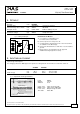
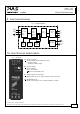
10. FRONT SIDE AND USER ELEMENTS
Fig. 10-1 Front side
A
Output Terminals
Screw terminals, dual terminals per pole
+ Positive output
- Negative (return) output
B
Input Terminals
Screw terminals
L1, L2 Phase input
PE (Protective Earth) input
C Output voltage potentiometer
Open the flap to set the output voltage. Factory set: 12.0V
D
DC-OK LED (green)
On when the voltage on the output terminals is > 10.5V
A
C
D
B
Jan. 2010 / Rev. 1.0 DS-CT5.121-EN
All parameters are specified at 12V, 8A, 400Vac, 25°C ambient and after a 5 minutes run-in time unless otherwise noted.
www.pulspower.com Phone +49 89 9278 0 Germany
9/21