
User manual


CT-Series: Power Supply Instruction Manual
CT-Serie: Bedienungsanleitung für Stromversorgung
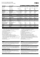
Technical Data
1)
Technische Daten
1)
CT5.121 CT5.241 CT10.241 CT10.481
Output Voltage Ausgangsspannung nom. DC 12-15V DC 24-28V DC 24-28V DC 48-56V
Factory Setting
6)
Werkseinstellung
6)
“Single-Use”, typ. 12.0V 24.1V 24.1V 48.0V
Output Current Ausgangsstrom nom. 8A (12V), 6.4A (15V) 5A (24V), 4.3A (28V) 10A (24V), 8.6A (28V) 5A (48V), 4.3A (56V)
PowerBoost
2)
- 6A (24V), 5.2A (28V) 12A (24V), 10.3A (28V) 6A (48V), 5.2A (56V)
Output Power Ausgangsleistung nom. 96W 120W 240W 240W
PowerBoost
2)
- 144W 288W 288W
Output Ripple & Noise Voltage
3)
Ausgangswelligkeit
3)
max. 100mVpp 50mVpp 50mVpp 100mVpp
AC Input Voltage AC Eingangsspannung nom.
2AC 380-480V
-15/+20%
2AC 380-480V
-15/+20%
3AC 380-480V
-15/+20%
3AC 380-480V
-15/+20%
Input Frequency Eingangsfrequenz nom.
50-60Hz
±6%
50-60Hz
±6%
50-60Hz
±6%
50-60Hz ±6%
AC Input Current
7)
AC Eingangsstrom
7)
400 / 480Vac, typ. 0.64A / 0.56A 0.75A / 0.68A 0.7/0.6A / Phase 0.7/0.6A / Phase
Power Factor
6)
Leistungsfaktor
6)
400 / 480Vac, typ. 0.44 / 0.42 0.45 / 0.43 0.53 / 0.52 0.53 / 0.52
Allowed Voltage Phase to Earth
5)
Erlaubte Spannung Phase zu Erde
5)
nom. AC 480V AC 480V AC 480V AC 480V
EN 61000-3-2 EN 61000-3-2 PFC-Norm Yes / Ja Yes / Ja Yes / Ja Yes / Ja
Input Inrush Current
4)
Einschaltspitzenstrom
4)
typ. 4A peak, 0.5A
2
s 4A peak, 0.5A
2
s 4A peak, 0.5A
2
s 4A peak, 0.5A
2
s
Hold-up Time
6)
Pufferzeit
6)
400 / 480Vac, typ. 33ms / 58ms 27ms / 48ms 34 / 54ms 34 / 54ms
Efficiency
6)
Wirkungsgrad
6)
400 / 480Vac, typ. 85.4% / 85.8% 90.4% / 90.0% 92.8 / 92.9% 92.8 / 92.9%
Power Losses
6)
Verlustleistung
6)
400 / 480Vac, typ. 16.4W / 15.9W 12.7W / 13.3W 18.6 / 18.6W 18.6 / 18.6W
Operational Temperature Range Betriebstemperaturbereich nom. -25°C - +70°C -25°C - +70°C -25°C - +70°C -25°C - +70°C
Output Derating Leistungsrücknahme 60°C … 70°C 2.5W/°C 3W/°C 6W/°C 6W/°C
Storage Temperature Range Lagertemperaturbereich nom. -40°C - +85°C -40°C - +85°C -40°C - +85°C -40°C - +85°C
Humidity
8)
Feuchte
8)
, IEC 60068-2-30 5 - 95% r.H. 5 - 95% r.H. 5 - 95% r.H. 5 - 95% r.H.
Vibration Schwingen IEC 60068-2-6 2g 2g 2g 2g
Shock Schocken IEC 60068-2-27 30g 6ms, 20g 11ms 30g 6ms, 20g 11ms 30g 6ms, 20g 11ms 30g 6ms, 20g 11ms
Degree of Pollution (not conductive) Verschmutzungsgrad (nicht leitend) EN 50178 / 62103 2 2 2 2
Degree of Protection Schutzart EN 60529 IP20 IP20 IP20 IP20
Class of Protection Schutzklasse IEC 61140 I
9)
I
9)
I
9)
I
9)
Over-temperature Protection
10)
Übertemperaturschutz
10)
OTP Yes / Ja Yes / Ja Yes / Ja Yes / Ja
Output Over-voltage Protection
10)
Überspannungsschutz Ausgang
10)
OVP, max. 20Vdc 32Vdc 32Vdc 60Vdc
Touch (Leakage) Current
11)
PE- Ableitstrom
11)
max. 0.18mA / 0.25mA 0.18mA / 0.25mA 0.22mA / 0.31mA 0.22mA / 0.31mA
Return Voltages Resistance
12)
Rückspeisefestigkeit
12)
max. 25Vdc 35Vdc 35Vdc 63Vdc
Parallel Use Parallelschaltbar Yes / Ja
13)
Yes / Ja
13)
Yes / Ja
14)
Yes / Ja
14)
Serial Use
15)
Serienschaltbar
15)
Yes / Ja Yes / Ja Yes / Ja Yes / Ja
Dimensions
16)
(WxHxD) Abmessungen
16)
(BxHxT) nom. 40x124x117mm 40x124x117mm 62x124x117mm 62x124x117mm
Weight Gewicht max. 500g; 1.1lb 500g; 1.1lb 750g; 1.65lb 750g; 1.65lb
Approvals Zulassungen 17) 17) 17) 17)
Limited Warranty Gewährleistung Years / Jahre 3 3 3 3
1) All parameters are specified at 3x400Vac (CT10) or 2x400Vac (CT5) input voltage, symmetrical
phase voltages, nominal output current, 25°C ambient and after a 5 minutes run-in time unless
otherwise noted. Mounting orientation: input terminals on the bottom and output terminals on top.
2) The PowerBoost is continuously allowed up to an ambient of 45°C. Above that temperature,
do not use the PowerBoost longer than 1 minute every 10 minutes.
3) 50-Ohm measurement, bandwidth 20MHz
4) Input inrush current electronically limited and is temperature independent.
5) According to IEC 60664-1
6) At nominal load and nominal input voltage.
7) At nominal load and the lower end of the input voltage.
8) Do not energize while condensation is present.
9) PE connection required (Ground).
10) Output shut-down with automatic restart attempts.
11) PE Leakage current at 3x440Vac, 50Hz / 3x528Vac, 60Hz, TT/TN-mains.
12) Loads such as decelerating motors and inductors can feed voltage back to the output of the
power supply. The figure represents the maximum allowed feed back voltage
13) Parallel use for a higher output power is allowed up to an ambient temperature of +45°C. A fuse (or
diode) on the output is required if more than three units are paralleled.
14) Set jumper on the front to “Parallel Use”. A fuse (or diode) on the output is required if more than
three units are paralleled.
15) Use only power supplies of the same type. The total output voltage should not exceed 150Vdc.
16) Depth without DIN-rail.
17) See datasheet or markings on the unit.
1) Alle Werte gelten bei 3x400Vac (CT10) oder 2x400Vac (CT5), symmetrische Phasenspannung,
Nennausgangsstrom, 25°C Umgebung und nach einer Aufwärmzeit von 5 Minuten, wenn nichts
anderes angegeben ist. Einbaulage: Eingang unten und Ausgang oben.
2) Der PowerBoost kann bis 45°C dauerhaft entnommen werden. Über 45°C darf der PowerBoost
nicht länger als 1 Minute alle 10 Minuten wiederholt werden.
3) 50-Ohm Messung, Bandbreite 20MHz
4) Der Einschaltstromstoß ist elektronisch begrenzt und temperaturunabhängig.
5) Gemäß IEC 60664-1
6) Bei Nominallast und Nenneingangsspannung.
7) Bei Nominallast und dem unteren Ende der Eingangsspannung.
8) Nicht betreiben, solange das Gerät Kondensation aufweist.
9) PE Verbindung erforderlich.
10) Ausgang schaltet ab und macht regelmäßig automatische Startversuche.
11) Erd-Ableitstrom bei 3x440Vac, 50Hz / 3x528Vac, 60Hz, TT/TN-Netze.
12) Bremsende Motoren oder Induktivitäten können Spannung zum Ausgang des Netzteils
rückspeisen. Der Wert gibt die max. zulässige Rückspeisespannung an.
13) Parallelschaltung zur Leistungserhöhung ist bis zu einer Umgebungstemperatur von +45°C
erlaubt. Bei mehr als drei Geräten eine Sicherung oder Diode zur Entkopplung verwenden.
14) Steckbrücke an der Front des Gerätes auf „Parallel Use“ umstellen. Bei mehr als drei Geräten
wird eine Sicherung oder eine Diode zur Entkopplung benötigt.
15) Nur gleiche Geräte bis zu einer Gesamtspannung von 150Vdc.
16) Tiefe ohne DIN-Schiene.
17) Siehe Datenblatt oder Prüfzeichen auf dem Gerät.
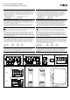
Installation
Use DIN-rails according to EN 60715 or EN 50022 with a height of 7.5 or 15mm. Mounting
orientation must be output terminals on the top and input terminals on the bottom. For other
orientations see datasheet. Do not obstruct air flow as the unit is convection cooled. Ventilation
grid must be kept free of any obstructions. The following installation clearances must be kept
when the power supplies are permanently loaded with more than 50% of the nominal current:
Left / right: 5mm (15mm in case the adjacent device is a heat source)
40mm on top, 20mm on the bottom of the unit.
Installation
Geeignet für DIN-Schienen entsprechend EN 60715 oder EN 50022 mit einer Höhe von 7,5 oder
15mm. Der Einbau hat so zu erfolgen, dass der Eingang sich unten und Ausgang sich oben
befindet. Für andere Einbaulagen siehe Datenblatt. Luftzirkulation nicht behindern! Das Gerät ist
für Konvektionskühlung ausgelegt. Es ist für ungehinderte Luftzirkulation zu sorgen. Folgende
Einbauabstände werden bei dauerhafter Belastung >50% des Nennstromes empfohlen:
Links / rechts: 5mm (15mm bei benachbarten Wärmequellen)
Oben: 40mm, unten 20mm vom Gerät.
Input Fuses
Internal input fuses: T3.15A (H.B.C.), not user accessible. The units are tested and approved for
branch circuits up to 32A. An external protection is only required if the supplying branch has an
ampacity greater than this, however, in some countries local regulations might apply. Check local
codes and requirements. If external fuses are necessary or utilized, minimum requirements need
to be considered to avoid nuisance tripping of the circuit breaker. A minimum value of 6A B- or 3A
C-Characteristic breaker should be used.
Sicherungen am Eingang
Die Geräte besitzen T3,15A (H.B.C.) Eingangssicherungen, die nicht anwenderzugänglich sind.
Die Geräte sind geprüft und zugelassen zum Anschluss an Stromkreisen bis max.32A. Ein
zusätzlicher externer Schutz ist nur erforderlich, wenn der Speisestromkreis mit einem höheren
Wert abgesichert ist oder nationale Richtlinien es vorschreiben. Falls externe Schutzelemente
verwendet werden, sollen diese nicht kleiner als 6A B- oder 3A C-Charakteristik sein, um ein
fehlerhaftes Auslösen zu vermeiden.
EMC Electromagnetic Compatibility
These power supplies are suitable for applications in industrial environment as well as in
residential, commercial and light industry environment without any restrictions. These devices
comply with FCC Part 15 rules. CE mark is in conformance with EMC directive 2004/108/EC as
well as the low-voltage directive (LVD) 2006/95/EC.
EMC Immunity: EN 61000-6-1, EN 61000-6-2
EMC Emission EN 61000-6-3, EN 61000-6-4, FCC Part 15 Class B
EMV Elektromagnetische Verträglichkeit
Diese Stromversorgungen erfüllen die Anforderungen für Anwendungen in industrieller Umgebung
und für den Wohn-, Geschäfts- und Gewerbebereich ohne Einschränkungen. Die Geräte erfüllen
auch die Anforderungen der FCC Teil 15. Das CE Zeichen ist angebracht und erklärt die Erfüllung
der EMV Richtlinie 2004/108/EG wie auch der Niederspannungsrichtlinie 2006/95/EG.
Störfestigkeit: EN 61000-6-1, EN 61000-6-2
Störaussendung: EN 61000-6-3, EN 61000-6-4, FCC Part 15 Klasse B