
User manual


CT-Series: Power Supply Instruction Manual
CT-Serie: Bedienungsanleitung für Stromversorgung
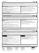
Terminals and Wiring
Use appropriate copper cables that are designed for a minimum operating temperatures of 60°C
(for ambient up to 45°C) and 75°C (for ambient up to 60°C). Follow national installation codes and
regulations! Ensure that all strands of a stranded wire enter the terminal connection! Up to two
stranded wires with the same cross section are permitted in one connection point (except for the
PE wire). Ferrules are allowed, but not required. In order to fulfill GL requirements, unused
terminal spaces must be closed.
Solid wire / Stranded wire / AWG 0.5-6mm
2
/ 0.5-4mm
2
/ 20-10 AWG
Wire stripping length 7mm / 0.28inch
Tightening torque 0.8Nm / 7lb.inch
Anschlussklemmen und Verdrahtung
Verwenden Sie geeignete Kupferkabel, die mindestens für 60°C bei einer Umgebungstemperatur
bis zu 45°C und 75°C bei einer Umgebungstemperatur bis zu 60°C zugelassen sind. Beachten
Sie nationale Bestimmungen und Installationsvorschriften! Stellen Sie sicher, dass keine
einzelnen Drähte von Litzen abstehen. Bis zu zwei Leiter mit gleichem Querschnitt sind in einem
Anschlusspunkt zulässig (außer beim Schutzleiter). Aderendhülsen sind erlaubt, aber nicht
erforderlich. Nichtbenutzte Klemmen zudrehen, um die GL Anforderungen zu erfüllen.
Starrdraht / Litze / AWG 0.5-6mm
2
/ 0.5-4mm
2
/ 20-10 AWG
Abisolierlänge 7mm / 0.28inch
Anzugsdrehmoment 0.8Nm / 7lb.inch
Output- and Overload Characteristic (see Fig. 5)
The units are overload, no-load, short-circuit proof. The units have a power reserve of 20%
included (except CT5.121). This extra power may even be used continuously at temperatures up
to +45°C. Furthermore, all CT10-units can deliver 3 times the nominal output current for 10ms at
reduced output voltage. This helps to trigger circuit breakers in faulty branches or helps to start
loads where motors or capacitors are involved.
At overload, the output current flows continuously. The unit does not switch-off or hiccup at
overload. Typical overload characteristics can be found in figure 5. The curves are valid for 24V
units. The other output voltages have an equivalent and proportional performance.
Ausgangs- und Überlastverhalten (siehe Bild 5)
Die Geräte sind leerlauf-, überlast- und kurzschlussfest. Die Geräte verfügen über 20%
Reserveleistung (außer CT5.121) die bis zu einer Umgebungstemperatur von 45°C dauerhaft
entnommen werden kann. Zusätzlich liefern alle CT10 Geräte für 20ms bis zum 3-fachen des
Nennstroms bei reduzierter Ausgangsspannung. Das hilft beim Starten von Motoren, beim
Einschalten von kapazitiven Lasten oder im Fehlerfall beim Auslösen von Sicherungen.
Bei Überlast fließt kontinuierlich Strom. Die Geräte schalten nicht ab und haben auch keinen
„Hiccup“ Modus. Typisches Überlastverhalten ist in Bild 5 gezeigt. Die Kennlinien gelten für 24V
Geräte. Andere Ausgangsspannungen zeigen ein proportional vergleichbares Verhalten.
Parallel-Use to Increase the Output Power
CT5:
Parallel use for a higher output power is allowed up to an ambient temperature of +45°C. A fuse
(or diode) on the output is required if more than three units are paralleled
CT10:
The output voltage shall be adjusted to the same value (±100mV) in “Single mode” at the same
load condition on all units, or shall be left with the factory settings. Afterwards, the jumper on the
front of the unit shall be moved from “single use” to “parallel use”, in order to achieve a load
sharing. The “Parallel Use” mode regulates the output voltage in such a manner that the voltage at
no load is approx. 5% higher than at nominal load. If no jumper is plugged in, the unit is in “Single
Use”. Factory setting is “Single Use”.
Parallelbetrieb zur Leistungserhöhung
CT5:
Parallelschaltung zur Leistungserhöhung ist bis zu einer Umgebungstemperatur von +45°C
erlaubt. Bei mehr als drei Geräten eine Sicherung oder Diode zur Entkopplung verwenden.
CT10:
Hierzu alle Geräte bei gleicher Belastung im „Single Mode“ auf ±100mV genau einstellen, oder die
Ausgangsspannung auf Werkseinstellung belassen. Danach die Steckbrücke an der Front des
Gerätes von „single use“ auf „parallel use“ umstecken, um eine Aufteilung des Laststromes
zwischen den Geräten zu erreichen. In „parallel use“ ist die Ausgangsspannung so geregelt, dass
diese im Leerlauf um etwa 5% höher ist als bei Nennlast. Ein nicht eingesteckter Jumper bedeutet
„single use“. Werkseinstellung ist „single use“.
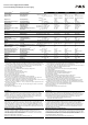
Dielectric Strength (see Fig. 3)
The output voltage is floating and separated from the input according to SELV (IEC/EN 60950-1)
and PELV (EN 60204-1, EN 50178; IEC 62103, IEC 60364-4-41) requirements. Type- and factory
tests are conducted by the manufacturer. Field tests may be conducted in the field using the
appropriate test equipment, which applies the voltage with a slow ramp (2s up and 2s down).
Connect all phase-terminals together as well as all output poles before the test is conducted.
A B C
Type Test (60s) 2500Vac 3000Vac 500Vac
Factory Test (5s) 2500Vac 2500Vac 500Vac
Field Test (5s) 2000Vac 2000Vac 500Vac
Isolationsfestigkeit (siehe Bild 3)
Die Ausgangsspannung hat keinen galvanischen Bezug zur Erde oder Schutzleiter und ist zum
Eingang nach den SELV (IEC/EN 60950-1) und PELV (EN 60204-1, EN 50178, IEC 62103, IEC
60364-4-41) Standards getrennt. Typ- und Stückprüfungen werden beim Hersteller durchgeführt.
Wiederholungsprüfungen dürfen mittels geeigneten Prüfgenerators mit langsam (2s) ansteigenden
und abfallenden Spannungsrampen in der Anwendung erfolgen. Vor den Tests sind alle Phasen
wie auch alle Ausgangspole miteinander zu verbinden.
A B C
Typprüfung (60s) 2500Vac 3000Vac 500Vac
Stückprüfung (5s) 2500Vac 2500Vac 500Vac
Wiederholungsprüfung (5s) 2000Vac 2000Vac 500Vac
CT10: Operation on Only 2-Phases (see Fig. 4)
No external protection device is required to protect against a phase-loss failure. The power
supplies are allowed to run permanently on two phases, when the de-rating requirements are
fulfilled. A long-term exceeding of the de-rating limits will result in a thermal shut-down of the unit
CT10: Betrieb an nur 2-Phasen (siehe Bild 4)
Es ist kein externer Schutz gegen Phasenausfall erforderlich. Die Stromversorgungen dürfen
dauerhaft an 2 Phasen betrieben werden, wenn die Ausgangsleistung temperaturabhängig
reduziert wird. Eine dauerhafte Überschreitung kann zu einer thermischen Abschaltung des
Gerätes führen.
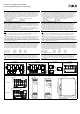
Fig. 1 / Bild 1
CT5: Functional Diagram / Funktionsschaltbild
Fig. 2 / Bild 2
CT10: Functional Diagram / Funktionsschaltbild.
Fig. 3 / Bild 3
Insulation / Isolation
Fig. 4 / Bild 4
CT10: 2-Phase Operation / Betrieb
+
+
-
-
V
OUT
Output
Over-
Voltage
Protection
PFC
Inductor
Inrush
Limiter
Transient
Filter
Input Fuses
Input Filter
Input
Rectifier
Output
Voltage
Regulator
Power
Converter
Output
Filter
Output
Power
Manager
Temper-
ature
Shut-
down
DC-ok
LED
L2
L1
+
+
-
-
V
OUT
Output
Over-
Voltage
Protection
PFC
Inductor
Inrush
Limiter
Transient
Filter
Input Fuses
Input Filter
Input
Rectifier
Output
Voltage
Regulator
Power
Converter
Output
Filter
Output
Power
Manager
Temper-
ature
Shut-
down
DC-ok
LED
L2
L3
L1
Single /
Parallel
A
C
B
L1
Input
Earth
Output
-
+
(L3)
L2
Allowed Output Power at 24V
0
-25 0 20
70°
C
48
96
144
192
240
288W
Ambient Temperature
40 60
A
.
.
.
2
x
3
4
0
-
5
7
6
V
a
c
,
3
x
3
2
0
-
5
7
6
V
a
c
B
.
.
.
2
x
3
2
0
-
3
4
0
V
a
c
A
B
Fig. 5 / Bild 5
Output Characteristic /Ausgangskennlinie; typ.
Fig. 6 / Bild 6 Physical Dimensions / Abmessungen
CT5 CT10 CT5 & CT10
CT5.241:
Output Voltage
0
048
4
8
12
28V
16
20
24
12A1062
Adjustment
Range
Output Current
CT10.241:
Output Voltage
(typ., single use)
0
0 6 12 18 24
4
8
12
28V
16
20
24
30
A
15932127
Adjustment
Range
Output Current
Extra
current
for 20ms
C
o
n
t
i
n
u
o
u
s
o
p
e
r
a
t
i
o
n
PU-380.011.00-10B