
Datasheet
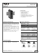


ML15.051
MiniLine-2
5V, 3A, SINGLE PHASE INPUT
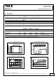
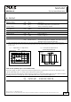
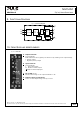
11. TERMINALS AND WIRING
All terminals are easy to access when mounted on the panel. Input and output terminals are separated from each
other (input below, output above) to help in error-free wiring.
Input Output
Type
screw terminals screw terminals
Solid wire 0.5-6mm
2
0.5-6mm
2
Stranded wire 0.5-4mm
2
0.5-4mm
2
American Wire Gauge 20-10 AWG 20-10 AWG
Wire stripping length 7mm / 0.275inch 7mm / 0.275inch
Screwdriver 3.5mm slotted or
Pozidrive No 2
3.5mm slotted or
Pozidrive No 2
Recommended tightening torque 1Nm, 9lb.in 1Nm, 9lb.in
Instructions:
a) Use appropriate copper cables that are designed for minimum operating temperatures of:
60°C for ambient up to 45°C and 75°C for ambient up to 60°C minimum.
b) Follow national installation codes and installation regulations!
c) Ensure that all strands of a stranded wire enter the terminal connection!
d) Up to two stranded wires with the same cross section are permitted in one connection point (except PE wire).
e) Do not use the unit without PE connection.
f) Screws of unused terminal compartments should be securely tightened.
g) Ferrules are allowed.
12. LIFETIME EXPECTANCY AND MTBF
These units are extremely reliable and use only the highest quality materials. The number of critical components such
as electrolytic capacitors has been reduced.
AC 100V AC 120V AC 230V
Lifetime expectancy
*) 66 000h 70 000h 93 000h at 5V, 3A and 40°C
> 15 years > 15 years > 15 years at 5V, 1.5A and 40°C
> 15 years > 15 years > 15 years at 5V, 3A and 25°C
MTBF
**) SN 29500, IEC 61709 2 479 000h 2 838 000h 2 686 000h at 5V, 3A and 40°C
4 066 000h 4 654 000h 4 405 000h at 5V, 3A and 25°C
MTBF
**) MIL HDBK 217F 1 175 000h 1 251 000h 1 145 000h at 5V, 3A and 40°C; Ground Benign GB40
1 575 000h 1 676 000h 1 534 000h at 5V, 3A and 25°C; Ground Benign GB25
*) The Lifetime expectancy shown in the table indicates the minimum operating hours (service life) and is determined by the lifetime
expectancy of the built-in electrolytic capacitors. Lifetime expectancy is specified in operational hours and is calculated according to the
capacitor’s manufacturer specification. The prediction model allows only a calculation of up to 15 years from date of shipment.
**) MTBF stands for Mean Time Between Failure, which is calculated according to statistical device failures, and indicates reliability of a
device. It is the statistical representation of the likelihood of a unit to fail and does not necessarily represent the life of a product.
The MTBF figure is a statistical representation of the likelihood of a device to fail. A MTBF figure of e.g. 1 000 000h means that
statistically one unit will fail every 100 hours if 10 000 units are installed in the field. However, it can not be determined if the failed unit
has been running for 50 000h or only for 100h.
Mar. 2013 / Rev. 2.1 DS-ML15.051-EN
All parameters are specified at 5V, 3A, 230Vac input, 25°C ambient and after a 5 minutes run-in time unless otherwise noted.
www.pulspower.com Phone +49 89 9278 0 Germany
10/22