
Owner manual

ML30 Instruction Manual for Power Supplies
ML30 Bedienungsanleitung für Stromversorgung
Technical Data
1)
Technische Daten
1)
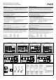
ML30.100 ML30.101 ML30.102 ML30.106
Output Voltage Ausgangsspannung nom. DC 24-28V DC 5-5.5V DC 10-12V
15)
DC ±12-15V
15)
Factory Setting at Full Load Werkseinstellung bei Nennlast typ. 24.5V 5.1V 12.0V
15)
±15.0V
15)
Output Current Ausgangsstrom nom. 1.3A at 24V
1.1A at 28V
5A at 5V
4.5A at 5.5V
3A at 10V
2.5A at 12V
±1.5A at ±12V
10)
±1.2A at ±15V
10)
Output Power Ausgangsleistung nom. 30W 25W 30W 36W
Output Ripple & Noise Voltage
2)
Ausgangswelligkeit
2
) max. 50mVpp 50mVpp 10mVpp 50mVpp
AC Input Voltage AC Eingangsspannung nom. AC 100-240V
-15%/+10%
AC 100-240V
-15%/+10%
AC 100-240V
-15%/+10%
AC 100-240V
-15%/+10%
Input Frequency Eingangsfrequenz nom. 50-60Hz 50-60Hz 50-60Hz 50-60Hz
AC Input Current
3)
AC Eingangsstrom
3)
typ. 0.51A / 0.33A 0.43A / 0.28A 0.51A / 0.33A 0.58A / 0.39A
Power Factor
3)
Leistungsfaktor
3)
typ. 0.56 / 0.47 0.55 / 0.46 0.56 / 0.47 0.56 / 0.47
Allowed Voltage L or N to Earth Erlaubte Spannung L oder N zu Erde max. 264Vac / 375Vdc 264Vac / 375Vdc 264Vac / 375Vdc 264Vac / 375Vdc
DC Input Voltage
13)
DC Eingangsspannung
13)
nom. DC 110-300V
-20%/+25%
DC 110-300V
-20%/+25%
DC 110-300V
-20%/+25%
DC 110-300V
-20%/+25%
Input Inrush Current
4)
Einschaltspitzenstrom
4)
typ. 17A / 35A 17A / 35A 17A / 35A 17A / 35A
Hold-up Time
3)
Pufferzeit
3)
typ. 46ms / 200ms 52ms / 230ms 46ms / 200ms 54ms / 236ms
Efficiency
3)
Wirkungsgrad
3)
typ. 87.1% / 87.8% 79.4% / 80.6% 84.9% / 85.8% 86.0% / 87.0%
Power Losses
3)
Verlustleistung
3)
typ. 4.6W / 4.3W 6.5W / 6.0W 5.3W / 5.0W 5.9W / 5.4W
Operational Temperature Range Betriebstemperaturbereich nom. -10°C - +70°C -10°C - +70°C -10°C - +70°C -10°C - +70°C
Output Derating Leistungsrücknahme +60°C to +70°C 0.8W/°C 0.5W/°C 0.8W/°C 1.0W/°C
Storage Temperature Range Lagertemperaturbereich nom. -40°C - +85°C -40°C - +85°C -40°C - +85°C -40°C - +85°C
Humidity
5)
Feuchte
5)
IEC 60068-2-30 5 - 95% r.H. 5 - 95% r.H. 5 - 95% r.H. 5 - 95% r.H.
Vibration Schwingen IEC 60068-2-6 2g 2g 2g 2g
Shock Schocken IEC 60068-2-27 15g 6ms, 10g 11ms 15g 6ms, 10g 11ms 15g 6ms, 10g 11ms 15g 6ms, 10g 11ms
Degree of Pollution (non-conductive) Verschmutzungsgrad (nicht leitend) EN 50178, IEC 62103 2 2 2 2
Degree of Protection Schutzart EN 60529 IP20 IP20 IP20 IP20
Class of Protection Schutzklasse IEC 61140 I
6)
I
6)
I
6)
I
6)
Over-temperature Protection Übertemperaturschutz OTP No / Nein No / Nein No / Nein No / Nein
Output Over-voltage Protection Überspannungsschutz am Ausgang OVP, max. 40Vdc 6.5Vdc 18Vdc 50Vdc
14)
Leakage Current
7)
TN/TT-mains PE- Ableitstrom
7)
TN/TT- Netze max. 0.23mA / 0.40mA 0.23mA / 0.40mA 0.23mA / 0.40mA 0.23mA / 0.40mA
IT-mains IT- Netze 0.49mA / 0.81mA 0.49mA / 0.81mA 0.49mA / 0.81mA 0.49mA / 0.81mA
Return Voltage Resistance
8)
Rückspeisefestigkeit
8)
max. 35Vdc 10Vdc 30Vdc ±20V
Parallel Use
11)
Parallelschaltbar
11)
- Yes / Ja Yes / Ja Yes / Ja No / Nein
Serial Use
12)
Serienschaltbar
12)
- Yes / Ja Yes / Ja Yes / Ja No / Nein
Dimensions
9)
(WxHxD) Abmessungen
9)
(BxHxT) nom. 45x75x91mm 45x75x91mm 45x75x91mm 45x75x91mm
Weight Gewicht max. 230g / 0.51lb 240g / 0.53lb 250g / 0.56lb 240g / 0.53lb
DC-OK Signal DC-OK Signal No / Nein No / Nein No / Nein No / Nein
1) All parameters are specified at 230Vac input voltage, TN- TT- IT-mains, nominal output
current, 25°C ambient and after a 5 minutes run-in time unless otherwise noted.
2) 50-Ohm measurement, bandwidth 20MHz
3) at 120Vac, 60Hz / 230Vac 50Hz
4) Peak value at 120Vac / 230Vac, at an ambient temperature of 40°C and cold start.
5) Do not energize while condensation is present.
6) PE connection required (Ground).
7) Leakage current at 132Vac, 60Hz / 264Vac, 50Hz
8) Loads such as decelerating motors and inductors can feed voltage back to the output of the
power supply. The figure represents the maximum allowed feed back voltage.
9) Depth without DIN-rail.
10) The +/– output voltage is generated by one converter. The sum of both voltages is regulated.
The total power of 36W can be drawn asymmetrically or only from one output. It is
recommended that the other output should draw a minimum load of 4% of the total load.
11) No current share between the units. Allowed up to 45°C ambient temperature. A fuse or diode
on the output of each unit is required if more than three units are connected in parallel.
12) Use only power supplies of the same type. The total output voltage should not be >150Vdc.
13) Use a battery or a similar DC source. Connect +pole to L and –pole to N. A supply from the
intermediate DC-bus of a frequency converter is not recommended and can cause a
malfunction or damage the unit. Additional tests might be necessary during the approval
process of a complete system.
14) Sum of both output voltages
15) The output voltage range can be set by a jumper (link between pin 4 and 5 of the output
terminals).
ML30.102: The output voltage will be 12V when the connection is installed. The voltage will
jump to 10V when removing this connection and then can be adjusted up to 12V.
ML30.106: The output voltage will be ±15V when the connection is installed. The voltage will
jump to ±12V when removing this connection and then can be adjusted up to ±15V.
1) Alle Werte gelten bei 230Vac, TN- TT- IT-Netze, Nennausgangsstrom, 25°C Umgebung und
nach einer Aufwärmzeit von 5 Minuten, wenn nichts anderes angegeben ist.
2) 50-Ohm Messung, Bandbreite 20MHz
3) bei 120Vac, 60Hz / 230Vac, 50Hz
4) Spitzenstrom bei 120Vac / 230Vac, einer Umgebungstemperatur von 40°C und Kaltstart.
5) Nicht betreiben, solange das Gerät Kondensation aufweist.
6) PE Verbindung erforderlich.
7) Ableitstrom bei 132Vac, 60Hz / 264Vac, 50Hz
8) Bremsende Motoren oder Induktivitäten können Spannung zum Ausgang des Netzteils
rückspeisen. Der Wert gibt die max. zulässige Rückspeisespannung an.
9) Tiefe ohne DIN-Schiene
10) Die +/– Ausgangsspannung wird von einem Wandler erzeugt und auf die Summenspannung
geregelt. Die 36W können unsymmetrisch oder nur von einem Ausgang entnommen werden.
Am anderen Ausgang wird eine Grundlast von 4% der entnommenen Leistung empfohlen.
11) Keine Stromaufteilung zwischen den Geräten. Erlaubt bis max. 45°C. Eine Sicherung oder
Diode je Ausgang ist erforderlich wenn mehr als 3 Geräte parallel geschaltet werden.
12) Nur gleiche Geräte bis zu einer Gesamtspannung von 150Vdc
13) Geeignet sind Batterien oder ähnliche Quellen. Den +Pol an L und –Pol an N anschließen.
Ein Betrieb am Zwischenkreis von Frequenzumrichtern wird nicht empfohlen und kann zu
Defekten oder Fehlfunktionen führen. Bei Zulassung eines Gesamtsystems können zusätzlich
Prüfungen erforderlich werden.
14) Summe der beiden Ausgangsspannungen
15) Die Ausgangsspannungsbereich kann mittels eines Jumpers (Verbindung zwischen Pin 4 und
5 der Ausgangsklemme gewählt werden.
ML30.102: Bei installierter Verbindung ist die Spannung 12V. Bei Entfernung der Brücke geht
die Spannung auf 10V und lässt sich dann mit dem Potentiometer bis 12V einstellen.
ML30.106: Bei installierter Verbindung ist die Spannung ±15V. Bei Entfernung der Brücke
geht die Spannung auf ±12V und lässt sich dann mit dem Potentiometer bis ±15V einstellen.
Installation
Use DIN-rails according to EN 60715 or EN 50022 with a height of 7.5 or 15mm. Mounting
orientation must be output terminals on top and input terminals on the bottom. For other
orientations see datasheet. Do not obstruct air flow as the unit is convection cooled. Ventilation
grid must be kept free of any obstructions. The following installation clearances must be kept
when power supplies are permanently fully loaded:
Left / right: 0mm (or 15mm in case the adjacent device is a heat source)
40mm on top, 20mm on the bottom of the unit.
Use in hazardous location areas
Units which are marked with "Class I Div 2" are suitable for use in Class I Division 2 Groups A, B,
C, D locations.
WARNING EXPLOSION HAZARDS!
Substitution of components may impair suitability for this environment. Do not disconnect the unit
or operate the voltage adjustment unless power has been switched off or the area is known to be
non-hazardous. A suitable enclosure must be provided for the end product which has a minimum
protection of IP54 and fulfils the requirements of the EN 60079-15:2010.
Installation
Geeignet für DIN-Schienen entsprechend EN 60715 oder EN 50022 mit einer Höhe von 7,5 oder
15mm. Der Einbau hat so zu erfolgen, dass sich die Eingangsklemmen unten und die
A
usgangsklemmen oben befinden. Für andere Einbaulagen siehe Datenblatt. Luftzirkulation nicht
behindern! Das Gerät ist für Konvektionskühlung ausgelegt. Es ist für ungehinderte Luftzirkulation
zu sorgen. Folgende Einbauabstände sind bei dauerhafter Volllast einzuhalten:
Links / rechts: 0mm (oder 15mm bei benachbarten Wärmequellen)
Oben: 40mm, unten 20mm vom Gerät.
Betrieb in explosionsgefährdeter Umgebung
Geräte, die mit "Class I Div 2" gekennzeichnet sind, sind für den Einsatz in Klasse I Division 2
Gruppen A,B,C,D Umgebung geeignet.
A
CHTUNG EXPLOSIONSGEFAHR!
Veränderungen am Gerät können die Tauglichkeit für diese Umgebung beeinträchtigen.
A
nschlüsse nicht abklemmen und Spannungseinstellung nicht verändern, solange Spannung
anliegt oder die Umgebung als explosionsgefährlich gilt. Das Gerät muss mindestens in ein IP54
Gehäuse, welches den Anforderungen der EN 60079-15:2010 entspricht, eingebaut werden.