
Datasheet


ML60.121
MiniLine
12V, 4.5A, SINGLE PHASE INPUT
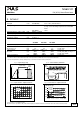
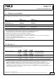
9. FUNCTIONAL DIAGRAM
Fig. 9-1 Functional diagram
Input Fuse
&
Input Filter
L
N
Output Over-
Voltage
Protection
Input
Rectifier
&
NTC
Inrush
Limiter
Power
Converter
Output
Voltage
Regulator
+
-
-
Output
Filter
+
V
OUT
DC
on
PE
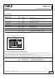
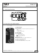
10. FRONT SIDE AND USER ELEMENTS
Fig. 10-1 Front side
A
Output Terminals
Screw terminals,
Dual terminals for the negative and positive pole. Both poles are
equal
+ Positive output
- Negative (return) output
B
Input Terminals
Screw terminals
L Phase (Line) input
N Neutral conductor input
PE (Protective Earth) input
C
DC-on LED (green)
On, when the voltage on the output terminals is > 9V
D
Output voltage potentiometer
(single turn potentiometer)
Turn to set the output voltage. Factory set: 12.0V
xxx. 201x / Rev. 1.1 DS--ML60.121-EN
All parameters are specified at 12V, 4.5A, 230Vac input, 25°C ambient and after a 5 minutes run-in time unless otherwise noted.
www.pulspower.com Phone +49 89 9278 0 Germany
9/22