
Data Sheet
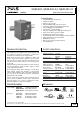

QS20.241, QS20.241-A1, QS20.241-C1
Q-Series
24V, 20A, SINGLE PHASE INPUT
INDEX
Page Page
1.
Intended Use .......................................................3
2. Installation Requirements...................................3
3. AC-Input...............................................................4
4. DC-Input...............................................................5
5. Input Inrush Current ...........................................5
6. Output .................................................................6
7. Hold-up Time.......................................................8
8. DC-OK Relay Contact ..........................................8
9. Efficiency and Power Losses................................9
10. Lifetime Expectancy and MTBF.........................10
11. Functional Diagram...........................................10
12. Terminals and Wiring........................................11
13. Front Side and User Elements...........................12
14. EMC....................................................................13
15. Environment ......................................................14
16. Protection Features ...........................................15
17. Safety Features ..................................................15
18. Dielectric Strength ............................................16
19. Approvals...........................................................17
20. Physical Dimensions and Weight......................18
21. Accessories ........................................................ 19
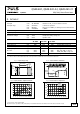
21.1. ZM2.WALL Wall Mounting Bracket .......19
21.2. ZM15.SIDE Side Mounting Bracket ........19
21.3. YR40 Redundancy Modules .....................20
22. Application Notes............................................. 21
22.1. Repetitive Pulse Loading..........................21
22.2. Peak Current Capability ...........................22
22.3. Back-feeding Loads ..................................22
22.4. External Input Protection.........................22
22.5. Charging of Batteries ...............................23
22.6. Output Circuit Breakers............................23
22.7. Parallel Use to Increase Output Power....24
22.8. Parallel Use for Redundancy ....................24
22.9. Series Operation .......................................25
22.10. Inductive and Capacitive Loads................25
22.11. Operation on Two Phases ........................25
22.12. Use in a Tightly Sealed Enclosure ............25
22.13. Mounting Orientations ............................26
The information presented in this document is believed to be accurate and reliable and may change without notice.
No part of this document may be reproduced or utilized in any form without permission in writing from the publisher.
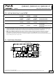
TERMINOLOGY AND ABREVIATIONS
PE and symbol PE is the abbreviation for Protective Earth and has the same meaning as the symbol .
Earth, Ground This document uses the term “earth” which is the same as the U.S. term “ground”.
T.b.d. To be defined, value or description will follow later.
AC 230V A figure displayed with the AC or DC before the value represents a nominal voltage with
standard tolerances (usually ±15%) included.
E.g.: DC 12V describes a 12V battery disregarding whether it is full (13.7V) or flat (10V)
230Vac A figure with the unit (Vac) at the end is a momentary figure without any additional
tolerances included.
50Hz vs. 60Hz As long as not otherwise stated, AC 230V parameters are valid at 50Hz mains frequency.
may A key word indicating flexibility of choice with no implied preference.
shall A key word indicating a mandatory requirement.
should A key word indicating flexibility of choice with a strongly preferred implementation.
Oct. 2013 / Rev. 2.2 DS-QS20.241-EN
All parameters are specified at 24V, 20A, 230Vac, 25°C ambient and after a 5 minutes run-in time unless otherwise noted.
www.pulspower.com Phone +49 89 9278 0 Germany
2/26