
Data Sheet

QS20.241, QS20.241-A1, QS20.241-C1
Q-Series
24V, 20A, SINGLE PHASE INPUT
4. DC-INPUT
DC input nom. DC 110-150V -20%/+25%
DC input range min. 88-187Vdc
DC input current typ. 4.6A 110Vdc, at 24V, 20A
Allowed Voltage L/N to Earth max. 375Vdc IEC 62103
Turn-on voltage typ. 74Vdc steady state value
Shut-down voltage typ. 69Vdc steady state value
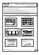
Fig. 4-1 Wiring for DC Input
Instructions for DC use:
+
-
Load
L
PE
+
-
Power Supply
AC
DC
Battery
N
a) Use a battery or similar DC source.
For other sources contact PULS
b) Connect +pole to L and –pole to N.
c) Connect the PE terminal to an earth wire or to the
machine ground.
5. INPUT INRUSH CURRENT
An active inrush limitation circuit limits the input inrush current after turn-on of the input voltage and after short
input voltage interruptions.
The charging current into EMI suppression capacitors is disregarded in the first microseconds after switch-on.
AC 100V AC 120V AC 230V
Inrush current max. 13A
peak
13A
peak
13A
peak
over entire temperature range;
mains interruptions > 750ms
typ. 11A
peak
9A
peak
7A
peak
over entire temperature range;
mains interruptions > 750ms
Inrush energy max. 5A
2
s 5A
2
s 5A
2
s over entire temperature range;
mains interruptions > 750ms
Inrush delay (A) typ. 400ms 400ms 650ms see (A) in Fig. 5-1
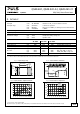
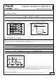
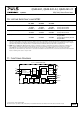
Fig. 5-1 Input inrush current, typical behavior
Input
Current
Input Voltage
Output
Voltage
A
A…. Inrush delay
Input: 230Vac
Output: 24V, 20A
Ambient: 25°C
Upper curve: Input current 5A / DIV
Middle curve: Input voltage 500V / DIV
Lower curve: Output voltage 20V / DIV
Time basis: 100ms / DIV
Oct. 2013 / Rev. 2.2 DS-QS20.241-EN
All parameters are specified at 24V, 20A, 230Vac, 25°C ambient and after a 5 minutes run-in time unless otherwise noted.
www.pulspower.com Phone +49 89 9278 0 Germany
5/26