
User manual


QS3.241
Q-Series
24V, 3.4A, SINGLE PHASE INPUT
Nov. 2006 / Rev. 1.0 DS-QS3.241-EN
All parameters are specified at 24V, 3.4A, 230Vac, 25°C ambient and after a 5 minutes run-in time unless otherwise noted..
www.pulspower.com Phone +49 89 9278 0 Germany
9/21
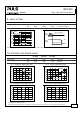
13. TERMINALS AND WIRING
Type Bi-stable, quick-connect spring clamp terminals. IP20 Finger safe construction.
Suitable for field- and factory installation. Shipped in open position.
Ferrules allowed, but not required
Pull-out force 10AWG:80N, 12AWG:60N, 14AWG:50N, 16AWG:40N (according to UL486E)
Input terminals Output terminals
Solid wire 0.5-6mm
2
0.3-4mm
2
Stranded wire 0.5-4mm
2
0.3-2.5mm
2
American wire gauge 20-10 AWG 26-12 AWG
Wire stripping length 10mm / 0.4inch 6mm / 0.25inch
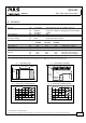
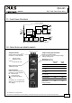
Fig. 13-1 Connecting a wire
1.
Insert the wire
2.
Snap the lever
To disconnect wire: same procedure
vice versa
Instructions:
a) Use appropriate copper cables that are designed
for an operating temperature of:
60°C for ambient up to 45°C and
75°C for ambient up to 60°C minimum.
b) Follow national installation codes and
installation regulations!
c) Ensure that all strands of a stranded wire enter
the terminal connection!
d) Up to two stranded wires with the same cross
section are permitted in one connection point
(except PE wire).
e) Do not use the unit without PE connection.
14. RELIABILITY
AC 100V AC 120V AC 230V
Lifetime expectancy min. 48 000h 62 000h 79 000h 40°C, 24V, 3.4A
min. 117 000h 126 000h 114 000h 40°C, 24V, 1.7A
min. 136 000h 15 years 15 years 25°C, 24V, 3.4A
MTBF SN 29500, IEC 61709 1 191 000h 1 265 000h 1 451 000h 40°C, 24V, 3.4A
2 061 000h 2 155 000h 2 436 000h 25°C, 24V, 3.4A
MTBF MIL HDBK 217F 581 000h 631 000h 643 000h 40°C, 24V, 3.4A, Ground Benign GB40
812 000h 889 000h 912 000h
25°C, 24V, 3.4A, Ground Benign GB25
The Lifetime expectancy shown in the table indicates the operating hours (service life) and is determined by the
lifetime expectancy of the built-in electrolytic capacitors.
Lifetime expectancy is specified in operational hours. Lifetime expectancy is calculated according to the capacitor’s
manufacturer specification. The prediction model allows a calculation of up to 15 years from date of shipment.
MTBF stands for Mean Time Between Failure, which is calculated according to statistical device failures, and indicates
reliability of a device. It is the statistical representation of the likelihood of the unit to fail and does not necessarily
represent the life of a product.