
Datasheet
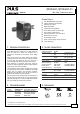


QT20.241, QT20.241-C1
Q-Series
24V, 20A, THREE PHASE INPUT
Oct. 2006 / Rev. 1.0 DS-QT20.241-EN
All parameters are specified at 24V, 20A, 3x400Vac, 25°C ambient and after a 5 minutes run-in time unless otherwise noted.
www.pulspower.com Phone +49 89 9278 0 Germany
2/23
INDEX PAGE
INDEX PAGE
1.
General Description ............................................1
2. Short-form Data ..................................................1
3. Order Numbers....................................................1
4. Markings ..............................................................1
5. AC-Input...............................................................3
6. DC-Input...............................................................4
7. Input Inrush Current ...........................................4
8. Output .................................................................5
9. Hold-up Time.......................................................7
10. DC-OK Relay Contact ..........................................7
11. Efficiency and Power Losses................................8
12. Functional Diagram.............................................9
13. Front Side and User Elements.............................9
14. Terminals and Wiring........................................10
15. Reliability...........................................................10
16. EMC....................................................................11
17. Environment......................................................12
18. Protection Features ...........................................13
19. Safety .................................................................13
20. Dielectric Strength ............................................13
21. Approvals...........................................................14
22. Fulfilled Standards............................................ 14
23. Used Substances ............................................... 14
24. Physical Dimensions and Weight..................... 15
25. Installation and Operation Instructions .......... 15
26. Accessory........................................................... 16
27. Application Notes............................................. 17
27.1. Repetitive Pulse Loading........................ 17
27.2. Peak Current Capability ......................... 18
27.3. Back-feeding Loads ................................ 18
27.4. Charging of Batteries............................. 18
27.5. Output Circuit Breakers ......................... 19
27.6. External Input Protection....................... 20
27.7. 2-Phase Operation.................................. 20
27.8. Parallel Use to Increase Output Power . 21
27.9. Parallel Use for Redundancy.................. 21
27.10. Daisy Chaining of Outputs..................... 21
27.11. Series Operation..................................... 22
27.12. Inductive and Capacitive Loads ............. 22
27.13. Use in a Tightly Sealed Enclosure .......... 22
27.14. Mounting Orientations .......................... 23
INTENDED USE
The power supply shall only be installed and put into operation by qualified personnel.
This power supply is designed for installation in an enclosure and is intended for the general use, such as in industrial
control, office, communication, and instrumentation equipment. Do not use this device in aircraft, trains and nuclear
equipment, where malfunctioning of the power supply may cause severe personal injury or threaten human life.
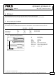
TERMINOLOGY AND ABREVIATIONS
PE and symbol PE is the abbreviation for Protective Earth and has the same meaning as the symbol .
Earth, Ground This document uses the term “earth” which is the same as the U.S. term “ground”.
T.b.d. To be defined, value or description will follow later.
AC 400V A figure displayed with the AC or DC before the value represents a nominal voltage with
standard tolerances (usually ±15%) included.
E.g.: DC 12V describes a 12V battery disregarding whether it is full (13.7V) or flat (10V)
As long as not otherwise stated, AC 380V and AC 400V parameters are valid at 50Hz and AC
480V parameters are valid at 60Hz mains frequency.
400Vac A figure with the unit (Vac) at the end is a momentary figure without any additional
tolerances included.
DISCLAIMER
The information presented in this document is believed to be accurate and reliable and may change without notice.