
Datasheet


QT20.241, QT20.241-C1
Q-Series
24V, 20A, THREE PHASE INPUT
Oct. 2006 / Rev. 1.0 DS-QT20.241-EN
All parameters are specified at 24V, 20A, 3x400Vac, 25°C ambient and after a 5 minutes run-in time unless otherwise noted.
www.pulspower.com Phone +49 89 9278 0 Germany
5/23
8. OUTPUT
Output voltage
nom. 24V
Adjustment range
min. 24-28V Guaranteed, multi turn potentiometer
max. 30V At clockwise end position of potentiometer
Factory setting
24.1V
±0.2%,
at full load, cold unit
Line regulation
max. 10mV 320 to 552Vac
Load regulation max. 100mV Static value, 0A Æ 20A Æ 0A
Ripple and noise voltage
max. 100mVpp 20Hz to 20MHz, 50Ohm
Output capacitance
typ. 950µF The energy of the bulk capacitor on the input side will be
transferred to the output to supply short load peaks.
Continuous power capability
Output current
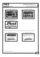
nom. 20A At 24V, see Fig. 8-1
nom. 17.5A
At 28V, see
Fig. 8-1
Output power nom. 480W 24V, continuous
nom. 490W 28V, continuous
Short-circuit current
min. 20A Load impedance 50mOhm, see Fig. 8-1
max. 23A Load impedance 50mOhm, see Fig. 8-1
BonusPower
®
, short term power capability (up to typ. 4s)
The power supply is designed to support loads with a higher short-term power requirement without damage or
shutdown. The short-term duration is hardware controlled by an output power manager. The BonusPower
®
is
repeatedly available. Detailed information can be found in chapter 27.1 .
Once BonusPower
®
has been stopped by the output power limiter, a timer disables the next BonusPower
®
capability.
The recovery timer will start as soon as the output voltage reaches the adjusted value again, which usually happens
after the load has been reduced.
Output current nom. 30A At 24V, see Fig. 8-1
nom. 26A
At 28V, see
Fig. 8-1
Output power nom. 720W 24V, short term
nom. 728W 28V, short term
Short-circuit current
min. 30A Load impedance 50mOhm, see Fig. 8-1
max. 34A Load impedance 50mOhm, see Fig. 8-1
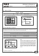
Bonus time
typ. 4s At 24V, 30A, duration until the output voltage dips,
min 3.5s See Fig. 8-2
max. 4.5s
BonusPower
®
recovery time
typ. 7s Overload free time to reset power manager, see Fig. 8-3
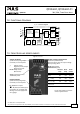
Peak current capability (up to several ms)
The power supply can deliver a peak current which is higher than the specified short-term current. This helps to start
current demanding loads or to safely operate subsequent circuit breakers.
The extra current is supplied by the output capacitors inside the power supply. During this event, the capacitors will
be discharged and causes a voltage dip on the output. Detailed curves can be found in chapter 27.2.
Peak current voltage dips typ. from 24V to 16V At 40A for 50ms
typ. from 24V to 19V
At 80A for 2ms
typ. from 24V to 16.5V
At 80A for 5ms