
Datasheet
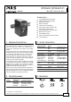


QT20.241, QT20.241-C1
Q-Series
24V, 20A, THREE PHASE INPUT
Oct. 2006 / Rev. 1.0 DS-QT20.241-EN
All parameters are specified at 24V, 20A, 3x400Vac, 25°C ambient and after a 5 minutes run-in time unless otherwise noted.
www.pulspower.com Phone +49 89 9278 0 Germany
9/23
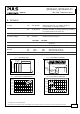
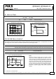
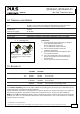
12. FUNCTIONAL DIAGRAM
Fig. 12-1 Functional diagram
+
+
-
-
V
OUT
DC
ok
Output
Over-
Voltage
Protection
PFC
Converter
Input Filter
Input Rectifier
Inrush Limiter
Transient Filter
Output
Voltage
Regulator
Power
Converter
Output
Filter
DC ok
Relay
Output
Voltage
Monitor
Output
Power
Manager
Temper-
ature
Shut-
down
Over-
load
DC
ok
L2
L3
L1
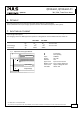
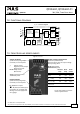
13. FRONT SIDE AND USER ELEMENTS
Fig. 13-1 Front side
Output voltage potentiometer
(multi turn potentiometer)
Open the flap to tune the output voltage.
Factory setting: 24.1V
DC-ok lamp (green)
Overload lamp (red)
Output Terminals
Quick-connect spring-clamp
terminals, no tools required
+ Positive output
- Negative (return) output
Dual pins per pole
DC ok Relay contact
(NO-contact)
Overload
lamp
DC-ok
lamp
DC-ok
contact
Normal mode OFF ON Closed
480W Continuous power /
720W Peak power
BonusPower
®
mode
OFF ON Closed
Overload
(V
OUT
< 90%)
ON OFF Open
Short-circuit
(V
OUT
= ca. 0V)
ON OFF Open
Over-
temperature
OFF ON
Open
Input Terminals
Quick-connect spring-clamp
terminals, no tools required
L1, L2, L3 Line inputs
... PE (Protective Earth) input
No input power OFF OFF Open
See chapter 14 “Terminals and
Wiring” to choose appropriate
wire gauges
DC-ok lamp and DC-ok contact
function synchronized