Please read and save these instructions. Read carefully before attempting to assemble, install, operate or maintain the product described. Protect yourself and others by observing all safety information. Failure to comply with instructions could result in personal injury and/or property damage, which Pumptec Inc. assumes no liability! Retain instructions for future reference.
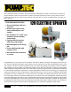
12V ELECTRIC SPRAYER Pumptec Operating Instructions and Parts Manual Unpacking DANGER! Remove all packing materials. Carefully remove the plunger pumps from the shipping carton. Inspect for any damage that may have occurred during transit. Check for any loose, missing or damaged parts. Warns about hazards that WILL cause serious person injury, death or major property damage if ignored. ___________________________________________ The contents includes 1 item: See page 10 and 11.
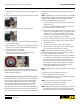
12V ELECTRIC SPRAYER Pumptec Operating Instructions and Parts Manual The pumping system can be mounted where it is visible, but it must be protected from rain, dirt and chemical spray or splashing. The pump must never be installed on a vertical surface with the pump head higher than motor, like a capital letter “T”, for example. POSITION MOTOR UNIT: 1. When selecting position, consider length and downward angle of suction line from tank to pump 2. Consider length of wire from battery to motor 3.
12V ELECTRIC SPRAYER Pumptec Operating Instructions and Parts Manual positive displacement pumps providing a specific amount of fluid constantly while operating. This volume of fluid must be directed out thru a nozzle or back to a tank because it cannot be stopped completely without creating excessively high pressure and risk of damage to pump, components, property and person.
12V ELECTRIC SPRAYER Pumptec Operating Instructions and Parts Manual 7. Allow time for air to purge from pump system and return to tank chemicals before completely testing pumping module and all connections. 8. Close bypass/agitation valve completely to pressurize system noTe: ALWAYS flush and rinse system after every use. NEVER change chemicals without completely rinsing tank and whole pumping system. ALWAYS read chemical label and exactly follow recommendations for system flushing. 1.
12V ELECTRIC SPRAYER Pumptec Operating Instructions and Parts Manual electrical connections. Can be panel or flush mounted. power interruption. 11. To shut down unit , push on-off switch in. DO NOT use the power selector as ON-OFF switch. 12. Open bypass valve on regulator to relieve system pressure. 13. Disconnect the trigger gun for safe storage. noTe: • Heavy-duty copper contacts. • For use with 6, 12, 24, and 32 volt systems.
12V ELECTRIC SPRAYER Pumptec Operating Instructions and Parts Manual Recommended Mounting of Cables at Switch • If a leak should occur after applying pressure to the reel, immediately discontinue supply line pressure. warning! Prevent static sparking. When working around flammables, ensure that the hose reel, hose and equipment are properly grounded. Use only grounded hose(s). Check continuity of ground circuit with ohmmeter. MOUNT REEL/FASTEN CRANK-HANDLE 1.
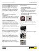
12V ELECTRIC SPRAYER Pumptec Operating Instructions and Parts Manual noTe: It is recommended that a swivel type connector be used to ease installation of outlet hose. 2. Thread male hose fitting into outlet riser(s). Refer to figure 1.0 Challenger series 112, 117, CM, DM and SM, outlet will be inside drum area. while tightening the outer nut. 3. Connect the supply line in the same manner. OPERATIONAL CHECKLIST • Check for correct operation by pulling out some of the hose/ cable.
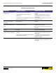
Pumptec Operating Instructions and Parts Manual 12V ELECTRIC SPRAYER Troubleshooting Chart Symptom Possible Cause(s) Hose/Cable wil not fully fit on to drum of reel 1. Hose/Cable is longer than specified. Reel keeps truning when operator stops pulling out hose/cable. 1. Tension drag brake is too loose causing hose/ cable backlash. 1. Adjust tension drag brake by turning fastener clockwise. No electrical current at output end of cable. (1125WC Series only) 1. Cable is severed. 2.
12V ELECTRIC SPRAYER Pumptec Operating Instructions and Parts Manual inleT CondiTion CHeCkliST Inadequate inlet conditions can cause serious malfunctions in the best designed pump. Surprisingly, the simplest of things can cause the most severe problems or go unnoticed to the unfamiliar or untrained eye. REviEW tHiS CHECKLiSt bEFoRE oPERAtion oF AnY SYStEM. Remember, no two systems are alike so there can be no onE best way to setup a system. All factors must be carefully considered.
12V ELECTRIC SPRAYER Pumptec Operating Instructions and Parts Manual through the lengths of hose. For example, a 3 GPM system will require (lose) 50 PSI per 50 ft. of 3/8” ID hose. A pump with only 60-70 PSI may not provide the desired performance at the end of the hose. See reference charts to assist in system design. bore. Verify that u-cup support ring is flush with top of u-cup. Place guide O-ring around guide and lightly grease. Press guide with O-ring installed into bore.
V ELECTRIC SPRAYER Pumptec Operating Instructions and Parts Manual tube. Slide plunger into one head assembly and then slide the other head onto plunger. Place head and plunger assembly on work surface with valves facing upward. 12. Install black grease from included packet into corners and center of plunger slot as shown. 9. Adjust plunger slot position towards center and have slot facing work surface. Replace all valves, O-rings and white washers.
12V ELECTRIC SPRAYER Pumptec Operating Instructions and Parts Manual Troubleshooting Chart Symptom Possible Cause(s) Corrective Action No water flow 1. Tank is empty or water is not turned on 1. Fill tank or turn on water supply 2. Filter clogged 2. Clean filter 3. Pump valves clogged or damaged 3. Examine valves and clean or replace 4. Pump has lost prime 4. Follow priming procedure 1. Worn nozzle 1. Replace nozzle with new one of same Low pressure size 2.
Pumptec Operating Instructions and Parts Manual 12V ELECTRIC SPRAYER LAWN AND PEST ELECTRIC SPRAY UNIT, 50 gALLON, mANUAL rEEL PN 80880 14 Version 110112
12V ELECTRIC SPRAYER Pumptec Operating Instructions and Parts Manual LAWN AND PEST ELECTRIC SPRAY UNIT, 50 gALLON, mANUAL rEEL PN 80880 Description part no Qty Description part no Qty 1 Sprayer Base, 5”Height, White W/50 Gallon Tank & Battery 40133 1 26 Grommet, 2- ½” Groove Diameter, 1/16” Groove Width C9010-0011 1 2 Hose Reel, 17.
Pumptec Operating Instructions and Parts Manual 12V ELECTRIC SPRAYER LAWN AND PEST ELECTRIC SPRAY UNIT, 50 gALLON, electric rEEL PN 80881 16 Version 110112
12V ELECTRIC SPRAYER Pumptec Operating Instructions and Parts Manual LAWN AND PEST ELECTRIC SPRAY UNIT, 50 gALLON, electric rEEL PN 80881 DESCRIPTION 1 Sprayer Base, 5” Height, White w/50 Gal Tank and Bat, HOLDER 2 Hose Reel, 17.5”, ½ NPT, 12 VDC RHM, W/Viton Seal, White 3 PARTS NO QTY DESCRIPTION PART NO QTY 1 27 Hose Barb, ½’ Male, ¾” Barb, Poly, Black 30424 1 30436 1 28 Agitator Horizon HA-HM 1 350U-190/M130-8, Sub-Assembly for Sprayer Assembly 80835 1 29 Clamp, Oetiker 30.
12V ELECTRIC SPRAYER Pumptec Operating Instructions and Parts Manual sUB-aSSEMBLY FOR sPRAYER ASSEMBLY 350u-190/m130-8, PN 80880 DESCRIPTION PART NO PART NO QTY 1 350U-190/M130-8, 12V, Viton, MValve, 4-3/8” Ports, Gold 80866 1 14 Nipple, ¾”, Hex, Poly, Black NIP-3/4-P 1 2 Regulator 9025, 145 PSI, Nylon, Black 70095 1 15 TEE, ¾” FFF, Poly, Black,SCH 80 30018 1 3 Plug, ½” Male, Hex , Poly PLUG-1/2 HEX-P 1 16 Ball Valve, ¾” Male X ¾” Female, Standard Blue Handle 30420 1 4 Pressure G
12V ELECTRIC SPRAYER Pumptec Operating Instructions and Parts Manual 350U-190/m30, 12V, VIton, m-vlave, 4-3/8” port, bd gold pn 80866 DESCRIPTION PART NO QTY 1 MOTOR, 1/4 HP, 12V, 30A, 42 FRAME M130 1 2 350U PUMP, VITON, M-VLAVE, 4-3/8” PORTS, GOLD 60074 1 3 KIT-C, .
12V ELECTRIC SPRAYER Pumptec Operating Instructions and Parts Manual repair Parts ILLUSTRATION for Plunger Pump 348U Description KIT A repair Parts list for Plunger Pump Part No. Qty Description 10013 KIT B Part No. Qty 10004 Plunger 1 Valve 4 O-Ring, 1-117 2 White Washer, 1/2” ID 8 Seal Ring 2 O-Ring, 1-116 4 O-Ring, 1-124 2 Retainer Plate * 2 Plunger Guide 2 Head * 2 Support Ring 2 Manifold * 1 U-Cup 2 O-Ring, 1-024 4 ( ) Sold only as part of a kit.
Pumptec Operating Instructions and Parts Manual 12V ELECTRIC SPRAYER LAWN & pEST, ELECTRIC SPRAY UNIT, electric REEL, pn: 80883/80881 21 Version 110112
Pumptec Operating Instructions and Parts Manual 12V ELECTRIC SPRAYER LAWN & pEST, ELECTRIC SPRAY UNIT, MANUAL REEL, pn: 80880/80882 22 Version 110112
Pumptec Operating Instructions and Parts Manual 12V ELECTRIC SPRAYER LIMITED WARRANTY Pumptec ONE-YEAR LIMITED WARRANTY. Pumptec PluNger PumPS, mODelS COVereD IN THIS mANuAl, Are WArrANTeD BY Pumptec, TO THe OrIgINAl uSer AgAINST DeFeCTS IN WOrKmANSHIP Or mATerIAlS uNDer NOrmAl uSe FOr ONe YeAr AFTer DATe OF PurCHASe. ANY PArT WHICH IS DeTermINeD TO Be DeFeCTIVe IN mATerIAl Or WOrKmANSHIP AND reTurNeD.