PT Series Ultraviolet Disinfection Systems MODEL: PT-8 PT-12 PT-20 It is important that those responsible for the installation of this equipment, as well as the owner / operator, read this manual and carefully follow the instructions and guidelines. Installation, Operation and Maintenance Manual CAUTION: Read and Follow all safety rules and operating instructions before first use of product. During normal operation, the Green LED will flash every 5 - 10 seconds.
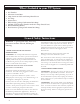
What's Included in your UV System 1. 2. 3. 4. 5. 6. 7. 8. 9. UV Chamber Electronic Control Box Lamp Connector Cable with Lamp Shroud Cover UV Lamp Quartz Sleeve Black O-Ring (packaged with manual & O-Ring) End Nut (located on UV Chamber under UV Lamp Shroud Cover) Bottom Mounting Bracket Flow Restrictor (packaged with manual & O-Ring) General Safety Instructions WARNING - to guard against injury, basic safety precautions should be observed, including the following: 1.
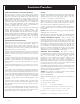
Function The function of this ultraviolet disinfection unit is to provide in excess of 99% reduction / inactivation of all water borne pathogenic (disease causing) bacteria. Model PT series have a number code designation correspondent to the maximum gpm (gallons per minute) flow rate of the unit. I.E.- PT-8 has a maximum flow capacity of 8 gpm. Applications: PT Units are designed for reduction / inactivation of micro-organisms in water supplies.
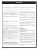
Installation GENERAL CONSIDERATIONS FOR ALL DISINFECTION UNITS: 1. When installing the equipment, it is necessary that the unit be isolated from vibration, heavy equipment, and poorly connected piping. 2. Incoming water temperature to the unit should not exceed 35° minimum to 110° maximum degrees Fahrenheit. 3. The operating pressure should not exceed 100 psi. 4. Before putting the unit into final operation follow sanitation procedures as outlined in this manual for proper disinfection.
Installation Continued the outlet valve and slowly open the inlet valve fully. Check the unit for leaks. If you find a leak at the brass end-nut, tighten the brass end-nut further. If the leak continues, drain the unit and inspect the quartz O-Ring and quartz sleeve for proper seal. Once you complete checking the unit, reassemble O-Ring and tighten brass end-nut. Repressurize the unit and check again. ULTRAVIOLET LAMP MAINTENANCE REQUIREMENTS: The U.V. lamp is rated for 9,000 hours of continuous use.
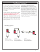
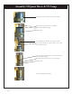
Assembly Of Quartz Sleeve & UV Lamp Locking Nut (screws down onto UV Chamber) Quartz Sleeve inserted into UV Chamber Quartz Sleeve Black O-Ring Locking Nut UV Lamp Harness Cable with Lamp Connector UV Lamp inserted into Quartz Sleeve with 4 Pin UV Lamp Connector UV Lamp Shroud (slides down over Brass End Nut and over black O-Ring) Brass End Nut (screws down onto S.S.
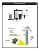
Installation Diagram PT-UV Chamber UV Lamp & Quartz Sleeve Pressure Tank (well systems) Pre-Filter Cartridge Water Softener (Water Filter Treatment Equipment) 1 Parts Breakdown: 1. 2. 3. 4. 5. 6. 7. 8.
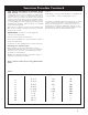
Sanitation Procedure HOW TO DISINFECT A WATER SYSTEM: Every new well, or existing water supply system that has been disrupted for service or repair, should be disinfected before it is returned to use. Water in the well and storage tank should be treated with a strong chlorine solution to destroy disease organisms. All pipelines and fixtures in the distribution system should be rinsed and flushed with chlorinated water. Upon installation of a U.V.
Sanitation Procedure Continued TOO MUCH CHLORINE IS BETTER THAN TOO LITTLE: **In situations where it is inconvenient to determine depth of water or diameter of a drilled well, a minimum of 1/2 gallon of household bleach may be used for wells up to 8 inches in diameter with estimated to be less than 80 feet deep; 1 gallon should be used for similar size wells with water deeper than 80 feet. In case of a well yielding more than 50 gallons per minute, special procedures are required.
Installation and Maintenance REQUIREMENTS FOR CLEANING THE QUARTZ SLEEVE: As water passes through the U.V., minerals, debris and other matter in the water may deposit onto the quartz sleeve. After sufficient film has formed on the quartz sleeve, the ability of the ultraviolet germicidal rays to pass though the quartz sleeve and into the water may be impaired. Therefore, it is necessary to determine a cleaning schedule for the quartz sleeve. The frequency will depend on the specific type of water conditions.
ED: 0" 2" Parts Breakdown Control Box ITEM NO. 7 PART NUMBER DESCRIPTION QTY. 1 PT-COGDS GDS Control Box Front Cover 1 2 PT-280 ATS-280 Circuit Board 1 3 07-00017 FUSE 1 4 PT1-421-GDS Workhorse Ballast 1 5 PT-BCOGDS GDS Control Box Back 1 6 PT-PTOP PT Overlay 1 7 PT-CBLFLB24 UV Cable & Shroud Assembly 1 8 PT-4003 Electrical Plug 1 9 562-738W-CX2-01 110 Outlet 1 10 PT-GDSCBBR ControlPART BoxNUMBER ITEM NO.
Parts Breakdown PT-8 ITEM NO. PART NUMBER DESCRIPTION QTY. 1 PT-476D Domed Quartz 1 2 PT4-450 UV Lamp 1 3 PT-5172 Sightport Lens 1 4 PT-5173 Orange .7" OD Viewport O Ring 1 5 PT-5171 Sightport Nut 1 6 PT5-409 Brass End Nut 1 7 PT8-544 Quartz Sleeve Black 1.2" OD ORing 1 8 PT5-410 Lock Nut 1 9 PT8-546 End UV Lamp Shroud Black 1.
Parts Breakdown PT-12 9 12 8 2 7 3 6 4 14 5 11 13 PART NUMBER DESCRIPTION QTY. PT1-759D PT4-739 1 1 3 PT-5173 4 5 6 PT-5172 PT-5171 PT5-410 7 PT8-544 8 PT5-409 9 PT8-546 10 PT-12GPM 11 STS-12GPM Domed Quartz UV Lamp Orange .7" OD Viewport O Ring Sightport Lens Sightport Nut Lock Nut Quartz Sleeve Black 1.2" OD ORing Brass End Nut End UV Lamp Black 1.5" OD O Ring 12 GPM Flow Control 12 Gallon Per Minute Feed Assembled Chamber Top Mounting Bracket 12 1 10 ITEM NO.
Parts Breakdown PT-20 ITEM NO. PART NUMBER DESCRIPTION QTY. 1 PT-832D Domed Quartz 1 2 PT4-810 UV Lamp 1 3 PT-5173 Orange .7" OD Viewport O Ring 1 4 PT-5172 Sightport Lens 1 5 PT-5171 Sightport Nut 1 6 PT5-410 Lock Nut 1 7 PT8-544 Quartz Sleeve Black 1.2" OD ORing 1 8 PT5-409 Brass End Nut 1 9 PT8-546 Black 1.
Wiring Diagram 8 6 7 5 4 RED RED RED RED YELLOW YELLOW YELLOW 2 3 1 D LAMP C BALLAST 281P CONTROL BOARD WHITE BLACK GREEN B YELLOW RED FEMALE OUTLET GREEN BLACK WHITE A MALE PLUG DRAWN PROPRIETARY AND CONFIDENTIAL THE INFORMATION CONTAINED IN THIS DRAWING IS THE SOLE PROPERTY OF AQUA TREATMENT SERVICES. ANY REPRODUCTION IN PART OR AS A WHOLE WITHOUT THE WRITTEN PERMISSION OF AQUA TREATMENT SERVICES IS PROHIBITED.
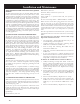
Troubleshooting TROUBLESHOOTING GUIDE PROBLEM CAUSE U.V. lamp will not light Check input voltage if below or above 120 volts CORRECTION Install a voltage regulator Line cord disconnected Check, replace or outlet defective Defective U.V.
Sterile Water Sample Procedures SUGGESTED PROCEDURE FOR OBTAINING STERILE WATER SAMPLES: Prior to taking the water sample, be sure to have on hand an adequate supply of sterile bottles These sterile bottles should be obtained from a reputable laboratory and should have been autoclaved and contained within a plastic outer wrapping. 1. Prior to taking the sample, it is imperative that the sample valve, faucets, etc. be opened at full force for a complete three and a half minutes. 2.
Specifications PT - 8 8 1 0.03 0.25 3/4" FNPT / 1" MNPT 21” x 3.5” x 3.5” 304 SS 9 lbs. PT - 12 12 1 0.03 0.25 3/4" FNPT / 1" MNPT 32” x 3.5” x 3.5” 304 SS 18 lbs. PT - 20 20 1 0.03 0.25 3/4" FNPT / 1" MNPT 35” x 5” x 5” 304 SS 21 lbs.
MANUFACTURER’S LIMITED WARRANTY REV. April, 2016 In accordance with the Manufacturer’s warranty, and subject to the conditions hereinafter set forth, American Water Service will repair or replace to the original user or consumer, equipment, parts or components found to be defective in manufacturing or workmanship. WARRANTY PERIODS: UV Chambers Electrical Components (excludes UV lamp) UV Lamp, Quartz Sleeve 10 yrs. 2 yr.