
Use and Care Guide


3
Function
Description
The function of this ultraviolet disinfection unit is to provide in excess of 99% reduction / inactivation of all water
borne pathogenic (disease causing) bacteria.
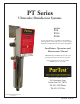
Model PT series have a number code designation correspondent to the maximum gpm
(gallons per minute) flow rate of the unit. I.E.- PT-8 has a maximum flow capacity of 8 gpm.
Applications: PT Units are designed for reduction / inactivation of micro-organisms in water supplies. The Ultraviolet
lamp peak radiation of 254 nanometer wavelength (nm) reduces or inactivates the D.N.A. (deoxyribonucleic acid) which
absorbs the Ultraviolet radiation. PT units meet minimum dosages of 30,000 microwatt second per square centimeter.
MAXIMUM CONCENTRATION LEVELS BEFORE ULTRAVIOLET:
Turbidity.................................5 NTU Hardness..........................................7 gpg
Color.......................................None Iron...................................................0.3 ppm
Manganese........................0.05 ppm pH....................................................6.5 - 9.5ppm
Important Note - Pre-filtration equipment may be required if these parameters cannot be maintained. Flow rate must
not exceed rated capacity of the unit.
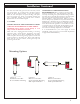
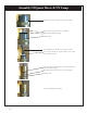
The PT series has an unique design with an ultraviolet germicidal lamp housed within a
single quartz sleeve surrounded by a stainless steel pressure chamber. The chamber is fabricated out
of 304 Stainless Steel.
These units come with an ultraviolet lamp designed with four pins at one end and a domed end quartz sleeve to protect
the UV lamp from direct contact with the water and a control box.
The quartz sleeve is intended to be placed through the disinfection chamber and will slightly protrude through the
threaded nipple. The ultraviolet lamp is placed within this quartz sleeve. The U.V. light shines through this specially
designed hard quartz sleeve for maximum disinfection efficiency to meet the requirements for bacteria reduction in
potable water.
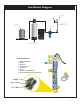
The inlet is located on the bottom of the chamber and the outlet can be located on the top side of the UV chamber
dependent upon the installation option selected. A sight Port is provided for safe and easy view of UV operation. A
bracket is secured to the wall and the chamber is held in place by tightening the lock nut to both mounting bracket and
chamber. A UV Control Box operates and monitors the UV Lamp status and provides visual and audible alarms when
the UV lamp is out or requires Lamp replacement.