
Use and Care Guide


4
Installation
GENERAL CONSIDERATIONS FOR ALL
DISINFECTION UNITS:
1. When installing the equipment, it is necessary that the
unit be isolated from vibration, heavy equipment, and
poorly connected piping.
2. Incoming water temperature to the unit should not
exceed 35° minimum to 110° maximum degrees Fahrenheit.
3. The operating pressure should not exceed 100 psi.
4. Before putting the unit into final operation follow
sanitation procedures as outlined in this manual for proper
disinfection. Sanitizing all discharge piping and fittings
with household bleach from disinfection unit to point
of use removes existing contaminants and gives the unit a
“clean start.” Be sure to rinse with U.V. treated water.
5. A flow control, included with the unit, must be
installed to insure only the designated flow through the
unit for proper disinfection.
GENERAL PRECAUTIONS TO BE FOLLOWED
AT ALL TIMES:
Only qualified persons or licensed professionals should be
involved in the installation or service maintenance of this
system. Contact PurTest with any questions prior to
working on this system.
1. Always disconnect electrical power to any U.V. unit
before servicing.
2. Under no circumstances should personnel look at a
U.V. lamp in operation (EXCEPT through an external
sight Port lens located on the outside of the unit).
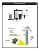
3. U.V. disinfection units must always be properly
grounded. The PT series are always placed after the
pressure tank and any other type of treatment devices (i.e.
softeners, filters).
These units are normally installed in a vertical position in
an enclosed area with good ventilation. Allow clearance of
at least the unit’s length at one end for quartz sleeve and
lamp replacement. Two (2) anchor bolt holes are provided
for proper wall support. Use wall plugs with screws for
sufficient support (not included). A lock nut secures the
mounting bracket to the U.V. chamber.
If your piping system is subject to impulse pressure
resulting in a “water hammer” condition, a surge tank or
other means must be provided to remove this condition;
otherwise, this extreme shock pressure condition may
rupture or fracture the quartz sleeve.
Make all plumbing connections to allow for ease of
service. Be sure to follow all local plumbing codes and
U.V. restriction requirements where specified by local
authorities.
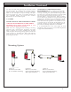
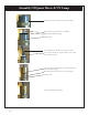
UV CHAMBER & CONTROL BOX MOUNTING
The UV Chamber and Control Box design allows for
several mounting configurations. The Control Box comes
standard mounted to the UV Chamber as shown in Option
A Installation Diagram on Page 5.
The Control Box may be removed and mounted on the
wall, with optional second mounting bracket, right next to
the UV Chamber as shown in Option B or C on the
installation diagram. (Wall mount screws are not included).
STEP BY STEP INSTALLATION:
1. Turn off the water before cutting into the water line.
2. Assess the installation (i.e. type of pipe, size of lines,
etc.) and obtain necessary plumbing fittings for installation.
Inlets and outlets on PT units are 3/4” FNPT and 1”
MNPT. Use Teflon tape on all threaded connections and
avoid over tightening.
Note: The flow control is a press in type. All UV
chambers come standard with a 3/4" FMPT connection
and a 1" MNPT connection on the Inlet / Outlet nipple.
Make sure the rubber part of the flow control is facing
outward from the bottom inlet. Simply hand press or
slightly tap in the flow control until it sits on the inside
ledge of the machined bottom inlet. (see Installation
Diagram on page 5)
3. Using the mounting bracket provided, secure unit to
wall, or other surface. Make sure to allow enough room
to install, replace, and clean the quartz sleeve and lamp.
Installing a water shut-off valve before and after the unit
is recommended to make servicing easy.
4. After mounting, install quartz sleeve, and O-Ring, per
Quartz Sleeve instructions on Page 8. Turn on the water
slowly, check for leaks, and repair as needed prior to full
service operation.
QUARTZ SLEEVE:
Installation of the Quartz Sleeve:
Always handle quartz sleeves carefully to prevent breaking
or chipping. The quartz sleeves are to be clean and free of
fingerprints before installing.
After unplugging the unit, remove the brass dust cap and
electrical connection. Then remove brass end nut. Install
the quartz sleeve through the stainless steel threaded nipple
until it is centered in the Quartz spring. Use a small amount
of O-Ring lubricant and install the O-Ring around the
Quartz Sleeves until it touches the S.S. nipple on the UV
Chamber. Avoid riding the O-Ring on any threaded part of
the nipple. Hand-tighten the brass end-nut to form a
compression seal around the quartz sleeve. Tightening the
end nut will lower the quartz sleeve into the spring assembly
compressing the O-Ring and providing a water tight seal.
When installed properly there is a small amount of space
left between the top of the quartz sleeve and the inside top
of end nut. Avoid overtightening the nut, which may cause
a fracture on the end of the quartz sleeve. Under normal
operation conditions, hand-tightening will provide a 100 psi
seal. Do not use any devices to tighten end nut.
After you have tightened the brass end nut and all other
plumbing connections, open the outlet valve. Slowly open
the inlet valve and flush out all remaining air. Then close