INSTALLATION & MAINTENANCE MANUAL POWER VT PLUS WATER HEATER MODELS (40, 50, 75, 90, 100) LX 125 A-PVIF MODELS (50, 75, 90, 100) LX (250, 300) A-PVIF Installation and service must be performed by a qualified service installer, service agency or the gas supplier. IMPORTANT: THIS MANUAL CONTAINS INFORMATION REQUIRED FOR INSTALLATION, OPERATION AND MAINTENANCE OF THIS EQUIPMENT.
Power VT® Plus WATER HEATER TABLE OF CONTENTS 1. 2. 3. 4. 5. 6. 7. 8. Safety Considerations Product Descriptions Water Heater Installation 3.1 Checking Equipment Before You Install 3.2 Codes 3.3 Electrical Requirements 3.4 Handling and Location 3.5 Service Clearances 3.6 Clearances to Combustible Surfaces General Piping Guidelines 4.1 Inlet and Outlet Connections 4.2 Building Return Piping Condensate Drain, Trap & Disposal 5.1 Condensate Neutralization System (optional) Gas Supply and Piping 6.
Power VT® Plus WATER HEATER 9. 10. 11. 12. 13. 14. 15. 16. 17. Operating and Safety Controls 9.1 Temperature and Pressure Relief Valve(s) 9.2 Operating Temperature Control 9.3 High Water Temperature Limit Control 9.4 Cathodic Protection 9.5 Electronic Low Water Cut-off (optional) TEMPTRAC Electronic Controller Panel 10.1 Principal of Operation 10.2 Upper LED Readout 10.3 Lower LED Readout 10.4 Control Buttons 10.5 To View the Setpoint 10.6 To Change the Setpoint 10.7 To Change Other Parameters 10.
Power VT® Plus WATER HEATER 1 SAFETY CONSIDERATIONS WARNING: If the information in the supplied manual(s) is not followed exactly, a fire, explosion or exposure to hazardous materials may result, causing property damage, personal injury or loss of life. FOR YOUR SAFETY Do not store or use gasoline or other flammable vapors or liquids in the vicinity of this or any other appliance. WHAT TO DO IF YOU SMELL GAS Do not try to light any appliance.
Power VT® Plus WATER HEATER IMPORTANT SAFETY NOTE It takes only 5 seconds of skin contact with 140°F water to cause a second degree burn! You must protect against high water temperatures at all lavatories, tubs, showers and other points of hot water contact. Accidental scalding from high water temperatures is a greater risk in some types of installations.
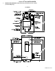
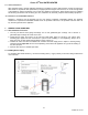
Power VT® Plus WATER HEATER 2 PRODUCT DESCRIPTION Component, Controls and Connection Locations (Locations May Vary) 125 SERIES 6 PV500-44 12/13
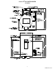
Power VT® Plus WATER HEATER 250 SERIES 7 PV500-44 12/13
Power VT® Plus WATER HEATER 300 SERIES 8 PV500-44 12/13
Power VT® Plus WATER HEATER 3 WATER HEATER INSTALLATION 3.1 Checking Equipment Before You Install Inspect the unit completely upon receipt from the freight carrier before signing the bill of lading. Inspect the appliance and all accompanying parts for signs of impact or mishandling. Verify the total number of pieces shown on packing slips with those actually received. Contact the freight carrier immediately if any damage or shortage is detected. 3.
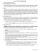
Power VT® Plus WATER HEATER 3.5 Service Clearances Allow sufficient space to provide adequate clearances on all sides for service and inspection. At least 24” above the water heater is required for filter replacement (if equipped) and burner/gas control service, 18” at left and right sides of the appliance. Optional equipment may increase the clearance requirements.
Power VT® Plus WATER HEATER SINGLE STORAGE WATER HEATER WITH SUPPLEMENTAL STORAGE TANK TWO WATER HEATERS WITH REVERSE RETURN PIPING 11 PV500-44 12/13
Power VT® Plus WATER HEATER 5 CONDENSATE DRAIN, TRAP & DISPOSAL The POWER VT PLUS water heater is designed to produce significant amounts of condensate because of its high efficiency. Condensate occurs naturally when water vapor in combustion gases is cooled below the dew point. Two 3/4” NPT drain connections are provided.
Power VT® Plus WATER HEATER 5.1 Condensate Neutralization System (optional) Although only slightly acidic (3-5 PH), condensate can be routed through an optional Condensate Neutralization System (see image below) to become pH neutral allowing for disposal into any drain or sewer system without concern for corrosion.
Power VT® Plus WATER HEATER 6.3 Inlet Pressure Measure at the inlet pressure tap located at the main gas cock. The inlet pressure must remain within the minimum and maximum values while the unit is at rest and while the unit is operating at maximum firing rate. INLET PRESSURE Maximum Static Pressure (Inches-Water Column) Minimum Flow Pressure (Inches-Water Column) NAT. GAS 14" 4.5" LP 14" 11" 6.
Power VT® Plus WATER HEATER MULTIPLE UNIT INSTALLATIONS GAS PIPING SIZE CHART Maximum Capacity of Pipe in Thousands of BTU’s per hour for gas pressures of 14 Inches Water Column (0.5 PSIG) or less and a pressure drop of 0.05 Inch Water Column (Based on NAT GAS, 1025BTU’s per Cubic Foot of Gas and 0.60 Specific Gravity).
Power VT® Plus WATER HEATER 7 COMBUSTION AND VENTILATION AIR Provisions for adequate combustion and ventilation air to the mechanical room must be in accordance with Section 5.3 “Air for Combustion and Ventilation” of the latest edition of the National Fuel Gas Code, ANSI Z223.1 and/or CAN/CSA B149, Installation Codes or applicable provisions of the local building codes. 7.1 Equipment Located In Confined Spaces Equipment located in confined spaces requires two openings installed within 12” (30.
Power VT® Plus WATER HEATER Duct Pipe: 90º Elbow 90º Long Radius Elbow 45º Elbow Duct Fitting Equivalent Length 6” Duct 7” Duct 8 feet 9 feet 5 feet 5 feet 5 feet 5 feet 8” Duct 10 feet 5 feet 5 feet 9” Duct 11 feet 6 feet 5 feet The following remote air duct information is provided for use in design calculations, if needed. Remote Air Duct Specifications Input MBtu Required Air (SCFM) 399 500 750 900 1000 87 108 163 195 217 7.
Power VT® Plus WATER HEATER 8 VENTING 8.1 Venting the Power VT Plus “SANI” models: Power VT Plus models with “SANI” in the model number are designed for operation only with stainless steel venting listed by UL, ULC, ETL or CSA for Category IV, positive pressure, gas appliance venting. Installation requires a field supplied stainless steel adapter from the 6-5/8 female economizer outlet to the specific size (six inch minimum) and model vent used.
Power VT® Plus WATER HEATER The following vent information is provided for use in design calculations, if needed. Venting Specifications Input MBtu Combustion Air Volume (cfm) Max Vent Press. ”W.C. 399 136 0.5 500 170 0.6 750 255 1.0 900 306 1.2 1000 340 1.3 8.4 CPVC Vent System Design, Construction and Assembly: The Power VT Plus water heater can be vented either vertically, through a ceiling or roof, or horizontally through a wall.
Power VT® Plus WATER HEATER 8.5 Vertical or Horizontal Vent Termination: 1. The vent terminal must have a minimum clearance of 4 feet (1.22 m) horizontally from, and in no case be located above or below, unless a 4 foot (1.22 m) horizontal distance is maintained from electric meters, gas meters, regulators and relief equipment. 2. The vent cap must terminate at least 3 feet (0.91 m) above any forced air inlet within 10 feet (3.05 m). 3. The vent shall terminate at least 4 feet (1.22 m) below, 4 feet (1.
Power VT® Plus WATER HEATER 9 OPERATING AND SAFETY CONTROLS WARNING: Turn off all electrical service to the appliance when accessing the limit or other controls located inside the control cabinet. This cabinet contains High Voltage wiring and terminals. If the electrical service is not turned off and these terminals are touched, a dangerous shock causing personal injury or loss of life could occur. Close and fasten the control cabinet cover before restoring electrical service to the appliance. 9.
Power VT® Plus WATER HEATER 10 TEMPTRAC™ ELECTRONIC CONTROLLER PANEL 10.1 Principle Of Operation The water heater operates to satisfy the setpoint of the TempTrac digital control whose sensor is located near the top of the water heater tank. Demand (flow) will typically create a drop in temperature, thus activating the water heater to add heat to the stored water. This setpoint is the desired water temperature to maintain. 10.
Power VT® Plus WATER HEATER 10.5 To View The Setpoint Push and release the SET key to see the set point value. To return to normal display, press SET + UP or wait 15 seconds without pressing any key. 10.6 To Change The Setpoint Push the SET key. The upper display will show the “St1” parameter name, while the lower display will show its value. Use the UP or DOWN key to cycle through the parameter names. Push the SET key to modify a parameter value.
Power VT® Plus WATER HEATER 10.8 LED Display Alarm Messages Alarm messages are displayed in the upper LED readout and alternate with the default display. An alarm LED ICON is also illuminated. (See TempTrac User Manual PV500-40 for full description.) ALARM MESSAGE 11 CAUSE RESULTS OF ALARM CONDITION RECOMMENDED ACTION Check wiring and sensor Terminals 14 & 17 “P1” TP1 probe failure Inlet temperature sensor is not connected or is reading incorrectly.
Power VT® Plus WATER HEATER 11.2 The Following Describes The Functions Of Each Of These Terminals And The Factory-Installed Options Required To Activate The Terminals: Note: Terminal P1-P2 are functional only when the water heater is equipped with the factory installed options required to activate the terminals. Terminals R1-R2, A1-A2, C1-C2 and T1-T2 are standard pre-wired functions on all models. R1-R2: Used to activate / de-activate water heater from remote master control.
Power VT® Plus WATER HEATER 4. Proof of Air Pressure Switch - The control will look for a signal from the airflow-proving switch, indicating that the blower is operating: a. When the airflow generated by the blower is sufficient to cause the differential air switch to close, the 15 second pre-purge delay will start. b. During this period any flue products or combustible gases which may have settled in the water heater are evacuated. 5.
Power VT® Plus WATER HEATER 13 INITIAL STARTUP 13.1 Initial Startup Requirements Installation should be complete prior to performing initial startup; and the startup must be complete prior to placing the water heater into service. Starting the water heater without proper piping, combustion air, venting or electrical systems can be dangerous and may void the product warranty.
Power VT® Plus WATER HEATER b. Attach a manometer to measure the gas pressure at the manual gas shutoff valve located just upstream of the gas train. Adjust gas train inlet pressure to the specified value (e.g. 14" W.C.), and tightly close the gas train manual shutoff valve closest to the burner. c. Reattach the manometer to the gas train manual shutoff valve at the burner and record the measured gas pressure in inches of water column (W.C.). Measure gas pressure again after 15 minutes.
Power VT® Plus WATER HEATER 19. When the blower motor starts, the flame control will check for a positive air flow. If the air switch or blocked filter switch (if equipped) is not made the blower will stay on for a period of time then lockout. To adjust the airproving switch, turn the adjustment screw counter-clockwise until the air proving light comes on, then turn the screw one turn counter-clockwise. The blocked filter switch (if equipped) should only be adjusted when the filter is new.
Power VT® Plus WATER HEATER Gas Train Illustration for Models 40 through 50 (Optional components may not be shown) Gas Train Illustration for Models 65 through 100 (Optional components may not be shown) 30 PV500-44 12/13
Power VT® Plus WATER HEATER 14 TROUBLESHOOTING GUIDE Problem Probable Cause Corrective Action Power Supply Check fuse and/or circuit breaker. Check voltage at 120/24V step-down transformer. On-Off Switch Check if On-Off switch is lighted. Check that the operating temperature control is set higher than the temperature of the water heater. Temperature Control Check for bad ground or bad control. Replace if necessary.
Power VT® Plus WATER HEATER 15 REPLACEMENT PARTS REPLACEMENT PARTS 32 PV500-44 12/13
Power VT® Plus WATER HEATER 15.
Power VT® Plus WATER HEATER 15.2 Control Panel Components (Optional components may not be included) Key No. Part No. Description Qty. U/M CONTROL, HOT SURFACE IGNITION FENWAL 1 EA 1 101947 2 - CONTROL, TEMPERATURE TEMPTRAC 1 EA 3 - DRIVE, VARIABLE FREQUENCY AC EMERSON 1 EA 4 5613 FUSEHOLDER, PANEL TYPE #HTB-28I 1 EA 5 5742 FUSE, MDA 15 AMP BUSS 250V NO SUBSTITUTE 1 EA 6 113915 LWCO, PROTODESIGN #LW-3-C-1-A-03 1 EA 7 58154 PROBE, LWCO WARRICK #3L1D002.
Power VT® Plus WATER HEATER 15.
Power VT® Plus WATER HEATER 15.4 Burner Assembly Components (Optional components may not be included) Item No. Qty. PVI Part No.
Power VT® Plus WATER HEATER 16 PERIODIC MAINTENANCE Listed below are items that must be checked to ensure safe reliable operations. Maintenance must be performed by a qualified service or maintenance provider. To ensure proper maintenance, the following instructions should be posted near the appliance and maintained in legible condition. Verify proper operation after servicing. WARNING: When servicing the controls, use exact, Factory authorized, replacement parts and label all wires prior to disconnection.
Power VT® Plus WATER HEATER 6. If equipped, the combustion air filter should be replaced every six months. If filter blockage becomes excessive the filter safety switch will not allow the burner to fire. To avoid nuisance shutdown in dirty environments, check and replace filter more frequently. 7. Inspect low water cutoffs and relief valves for proper operation at every six months, or more often if indicated by inspection. 8.
Power VT® Plus WATER HEATER 17 RECOMMENDED MAINTENANCE SCHEDULE 1. Annual Maintenance a. b. c. d. e. f. g. h. i. 2. Semi-Annually a. b. c. d. e. f. g. h. 3. Test low-water cutoff device and alarm (if equipped). Check flue, vent, stack, or outlet dampers. Check flame signal strength. Check flame failure detection system. Check firing rate control. Listen to and visually check the pilot and main fuel valves. Daily Maintenance a. b. 5. Recalibrate all indicating and recording gauges.
Power VT® Plus WATER HEATER PVI INDUSTRIES®, LLC 3209 Galvez Ave. Fort Worth, Texas 76111 Phone 1-800-433-5654 www.pvi.