PLCD10CH OPERATING INSTRUCTIONS 10 DIGITAL AUDIO COMPACT DISC CHANGER Open Disc Magazine Compact Disc Changer System Disc Auto Changer Compact Disc Auto Changer
CONTENTS HINTS FOR CORRECT AND SAFE OPERATION HOW TO USE THE MAGAZINE PRECAUTIONS FOR HANDLING DISCS INSTALLATION PARTS WIRING RESET FUNCTION BEFORE INSTALLING THE UNIT • Transport Lock Screws • Installation and Wiring Precautions • Position of the built-in anti-vibration Board INSTALLATION • Procedure for Installation on Carpet (Horizontal Position) • Procedure for Installation on Carpet (Vertical Position) • Procedure for Installation on Carpet (At a 45° angle) • Procedure for Installation (Suspended Posi
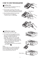
HOW TO USE THE MAGAZINE Loading a disc 1. Pick the tab on the magazine’s disc tray and pull out only of the trays. 2. Place the disc on the tray with its play surface facing down (label surface facing up). • Each tray can accommodate only one disc. Label side up 3. Press the tab on the disc tray to store the tray back in the magazine. • Up to ten discs can be loaded. Play side down Installing the magazine 1. Slide the door toward the right. 2.
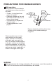
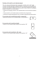
PRECAUTIONS FOR HANDLING DISCS With new discs The symptoms described below sometimes occur when new discs are used: • The disc is not played even when it is loaded. • Operation changes to the next disc before the first disc has a chance to be played. • The same disc is played over and over again. • The designated disc is not played. Burrs Burrs Center hole Outside circmference Remove all plastic particles of burr from surfaces of disc before loading in magazine.
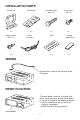
INSTALLATION PARTS Bracket (A) Bracket (B) Hexagonal Bolt (M6 x 12) Truss Screw (M4 x 5) x2 x2 x4 x4 Tapping Screw (M5 x 12) DIN 8 Pin Cable Seal Double Sided Tape x4 x1 x1 x2 WIRING Connect this cable to the terminal of the CD player. RESET FUNCTION The reset button must be activated with either a ball point pen or thin metal object. It is to be activated for the following reason: • Initial installation of the unit when all wiring is completed. • Some functions do not operate.
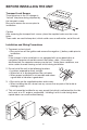
BEFORE INSTALLING THE UNIT Transport Lock Screws The mechanism in the CD changer is “locked” into place during shipment by the transport screws. Be sure to remove the screws prior to installation. Caution After removing the transport lock screws, place the supplied seals over the screw holes. These seals are used to keep dust, which could cause a malfunction, out of the unit. Installation and Wiring Precautions 1. To prevent a short-circuit.
Position of the built-in anti-vibration board This unit can be installed horizontally (suspended), vertically, and at a 45° angle. Once the installation position has been decided, it’s necessary to set the position of the built-in anti-vibration board inside the unit. Please do this before performing the procedure listed below. Vibration may cause the disc to skip if the unit is used before properly setting the anti-vibration board.
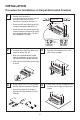
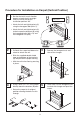
INSTALLATION Procedure for Installation on Carpet (Horizontal Position) 1 • Confirm that the built-in anti-vibration boards on both the left and right sides are set to the horizontal installation position “0”. Built-in anti-vibration board position Hexagon bolts (M6 x 12) • Attach the left and right brackets (A) using the hexagonal bolt (M4 x 5). • Attach the left and right brackets (A) to their respective brackets (B) using the hexagonal bolts (M6 x 12) and the hexagonal nuts (M6).
INSTALLATION Procedure for Installation on Carpet (Vertical Position) 1 • Set that the built-in anti-vibration boards on both the left and right sides are set to the vertical installation position “90”. Built-in anti-vibration board position Hexagon bolts (M6 x 12) • Attach the left and right brackets (A) using the hexagonal bolt (M4 x 5). • Attach the left and right brackets (A) to their respective brackets (B) using the hexagonal bolts (M6 x 12) and the hexagonal nuts (M6).
INSTALLATION Procedure for Installation on Carpet (at a 45° angle) 1 • Set the built-in anti-vibration boards on both the left and right sides to the 45° installation position “45°”. Built-in anti-vibration board position • Attach the left and right brackets (A) using the hexagonal bolt (M4 x 5). Hexagon bolts (M6 x 12) • Attach the left and right brackets (A) to their respective brackets (B) using the hexagonal bolts (M6 x 12) and the hexagonal nuts (M6).
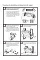
INSTALLATION Procedure for Installation (Suspended Position) 1 • Confirm that the built-in anti-vibration boards on both the left and right sides are set to the horizontal installation position “0”. Built-in anti-vibration board position • Attach the left and right brackets (A) using the hexagonal bolt (M4 x 5). Hexagonal Bolts Hexagonal Bolts 2 3 • Determine the mounting location and drill four mounting holes. 3.6ø 11 • Attach the CD changer with the tapping screws (M5 x 12).
HANDLING THE DISCS Dirt, dust, scratches and warpage cause sound skips during playback and a deterioration of sound quality. How to take care of your disc: 1. Use compact discs that have the mark shown on the right. 2. Fingerprints and dust should be carefully wiped off the disc’s signal surface (glossy side) with a soft cloth. Unlike conventional records, the compact disc has no grooves to collect dust and microscopic debris, so gently wipe with a soft cloth should remove most particles.