
Operating instructions


Page 6
Connections
Below is a description of each of the connectors. The connections are
described in numeric order, followed by video, network and power
connections.
CON1
CON1 is for the PCB power connection. This power controls the
switching of the relays, the video gain and lift and the lens functions. AC
power for the P/T head and auxiliaries is connected separately to CON5.
The PCB requires a +12V DC ± 10%, 1A class 2 power supply, this is
already connected.
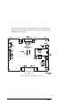
Referring to figure 1 connect the +12V DC and 0V (return) to CON1.
If the polarity is correct when the power is switched on then LED1 (see
figure 1) is green. It appears red for an incorrect polarity.
CON2
If you are using a preset P/T head and lens then CON2 provides the
supplies and feedback (FB) connections for the pot-wiper circuits. The
direction of the feedback is automatically calculated when the test routine
is invoked (see Testing on page 9), this means it is not necessary to wire
the pots in a specific direction.
Referring to figure 1, connect CON2 to the preset pots on the P/T head
and the lens. Connect any unused feedback inputs to ground.
Make a note on your module description sheet of the preset connections
and the type of lens.
CON3
CON3 contains the lens drive outputs for focus, iris and zoom. The drive
voltage is +10V DC at up to 100 mA.
Refer to your lens instructions and connect up your lens according to
figure 1.
CON4
CON4 contains the power output connections for your P/T head and
auxiliaries (AUX A, AUX B, AUX C and AUX D).