
Operating instructions


Page 9
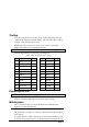
Testing
Your AC receiver has an on board test procedure which steps through
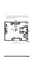
outputs in the sequence shown in Table 1. The test push button is shown
in figure 1. The test takes 55 seconds.
Running the test procedure also allows your receiver to detect the
feedback polarities for your P/T head and lens.
WARNING : Your AC receiver PCB now contains live voltages
Using an appropriate tool, press the test push button.
Step Action Time Step Action Time
1 Right & Down 5s 12 Zoom Out 3s
2 Pause 2s 13 Zoom In 3s
3 Pan Left 3s 14 Pause 2s
4 Pan Right 3s 15 Iris Close 3s
5 Pause 2s 16 Iris Open 3s
6 Tilt Up 3s 17 Pause 2s
7 Tilt Down 3s 18 AUX A 2s
8 Pause 2s 19 AUX B 2s
9 Focus Near 3s 20 AUX C 2s
10 Focus Far 3s 21 AUX D 2s
11 Pause 2s 22 Exit
Replacing the Lid
WARNING : Refit the lid securely to prevent unauthorised access
Tighten the four securing screws with an appropriate tool until they
cannot be undone by hand. Do not exceed a torque of 4 Nm.
Maintenance
Once your AC receiver is correctly installed and commissioned it
requires no routine maintenance.
Changing the Fuse
The fuse holder (see figure 1) contains a 10A A/S fuse for protecting the
relay outputs.
To replace the fuse, switch off all power to the module, turn the top anti-
clockwise using an appropriate tool, change the fuse and replace the top.
Table 1. The Automatic Test Sequence