QSTD5304 Digital Video Recorder User Manual QSTD5304 DVR User Manual For H.
QSTD5304 Digital Video Recorder User Manual CONTENTS CHAPTER 1 Introduction ................................................................................. 4 1.1 DVR Introduction.......................................................................................... 4 1.2 Main Features and Functions....................................................................... 4 CHAPTER 2 Panel Functions .......................................................................... 6 2.1 Check Accessories.........
QSTD5304 Digital Video Recorder User Manual CHAPTER 5 Operation with Mouse............................................................... 48 5.1 Switch Channel .......................................................................................... 48 5.2 Enter Menu List.......................................................................................... 48 5.2.1 Search ..................................................................................................................... 48 5.2.
QSTD5304 Digital Video Recorder User Manual CHAPTER 1 Introduction 1.1 DVR Introduction This DVR uses Dual Stream technology, and standard H.264 algorithm, combined with a fashionable outline design and the latest advanced video compression format, with a main processor that can process recorded video and internet transmission simultaneously at different bit rates and has a distinct independent LCD monitor embedded on the front panel.
QSTD5304 Digital Video Recorder User Manual PTZ CONTROL • Supports various PTZ protocols • Supports 16 PTZ presets • Supports remote PTZ control COMMUNICATION PORT FOR PTZ CAMERAS • RS 485 communication port NETWORK • Supports TCP/IP protocol • Supports remote DVR configuration • Supports static IP, dynamic IP (DHCP) and PPPoE • Supports DDNS: Pending • Real-time live surveillance, remote playback and remote backup • Remote PTZ control and Preset setting • Supports IE browser • Supports Central Management
QSTD5304 Digital Video Recorder User Manual CHAPTER 2 Panel Functions Warning: Please power off the DVR before you connect other devices to it. 2.1 Check Accessories When you receive the unit please check the accessories and make sure you have all of the parts. Normally, accessories will include one mouse, a power cable, manual, and some screws for installing HDD.
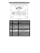
QSTD5304 Digital Video Recorder User Manual Items 1 2 Names RECORD /SEARCH 3 +/REW 4 -/FF 5 ESC/STOP 6 7 8 9 MENU IR Receiver Enter button Direction button 10 USB Functions Record manually 1. Suspend 2. Enter search mode in live view 1. Increase the value in setup mode 2. Rewind 1. Decrease the value in setup mode 2. Fast forward 1. Exit the current interface or status 2.
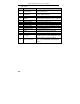
QSTD5304 Digital Video Recorder User Manual 2.3 Rear Panel Layout subject to change, may be slightly different from your model. The rear panel sketch and interface buttons are shown as Fig 2.2 Fig 2.2 Back Panel Items 8 Names Functions 1 2 ALARM IN ALARM OUT Connect to external sensor 1-4 Relay output. Connect to external alarm.
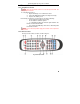
QSTD5304 Digital Video Recorder User Manual 2.4 Remote Control Introduction 2.4.1 Using Remote Control Notice: Please note that Remote Control is not a standard part of this DVR. Your package might not include it. To setup Remote Control: 1. Open the battery cover of Remote Control. 2. Put in two AAA batteries with poles aligned correctly. 3. Replace the battery cover.
QSTD5304 Digital Video Recorder User Manual The functions of the buttons on the Remote Control are described in the table below: Items 1 Power Button 2 INFO Button 3 12 13 REC Button Number and Letter Buttons Multi-Screen Button SEARCH Button MENU Button ENTER Button Direction Button +/- Button Playback Control Button AUDIO Button Auto Dwell Button 14 A 15 PTZ Control Button 4 5 6 7 8 9 10 11 10 Names Button Functions Start shutdown to stop firmware running. Do it before powering off.
QSTD5304 Digital Video Recorder User Manual CHAPTER 3 Basic Operation Guide 3.1 How to Start DVR Notice: Before powering on the unit, please make sure the power input matches the local power voltage. To start the DVR: STEP1 Connect the DVR to AC adaptor and plug in. STEP2 Turn on the DVR. STEP3 Wait for the DVR to initialize. After DVR is powered on, ‘STARTING……’ appears on the screen, which indicates the DVR is initializing. After ‘WELCOME’ is displayed, you enter into live display mode.
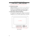
QSTD5304 Digital Video Recorder User Manual The structure of the main menu is shown in Fig 3.3. BASIC CONFIG LIVE CONFIG RECORD CONFIG MOTION ALARM ALARM CONFIG SENSOR ALARM PTZ CONFIG OTHER ALARM USER CONFIG BASIC CONFIG NETWORK IP CONFIG SHUTDOWN SYSTEM DISK MANAGEMENT MENU SYSTEM LOG SYSTEM INFO UPDATE FIRMWARE DDNS CONFIG MANAGER TOOLS LOAD DEFAULT CLEAR ALARM OUT Fig 3.3 Structure of Main Menu 3.2.1 Basic Configuration Basic Configuration menu is shown as Fig. 3.4. Fig 3.
QSTD5304 Digital Video Recorder User Manual 2. TIME POSITION This item is for setting up the position of the time on the display. There are three options: TOP: Time is displayed on top of the screen. BOTTOM: Time is displayed at the bottom of the screen. NO: Time is not displayed on the screen 3. Language There are languages to be selected English or Spanish. 4. DVR NAME Users can set DVR name with letters from ‘a’ to ‘z’ or numbers from ‘0’ to ‘9’.
QSTD5304 Digital Video Recorder User Manual 3.2.2 Live Configuration Live Configuration menu is shown in Fig. 3.6. Fig 3.6 Live Configuration 1. CHANNEL STEP1 Move the cursor to the item. STEP2 Press "Enter" key to select the channel 2. CHANNEL NAME User can set the channel name with letters from ‘a’ to ‘z’ or numbers from ‘0’ to ‘9’. STEP1 Press "A" button to switch the inputting mode between letters and numbers. STEP2 Enter channel name. STEP3 Press "Enter" key to confirm the operation. 3.
QSTD5304 Digital Video Recorder User Manual 3.2.3 Record Configuration Record Configuration menu is shown in Fig. 3.7. Fig3.7 Record Configuration 1. VIDEO RESOLUTION This unit supports CIF format. Resolutions of different video formats are: PAL: 352*288(CIF); NTSC: 352*240(CIF) 2. RECYCLE Checking the "RECYCLE" option means once the hard drive is filled the DVR will continue to record by covering the previous recording automatically, starting with the oldest.
QSTD5304 Digital Video Recorder User Manual 8. SCHEDULE RECORD Schedule Record Setup is shown as Fig. 3.8. Fig 3.8 Schedule Setup STEP1 STEP2 up. STEP3 Move the cursor to "SCHEDULE RECORD" option Check "SCHEDULE RECORD", and the “Setup” window will pop Press "Setup" to enter the Schedule Setup menu. Press "ESC" button on the front panel to get back to upper menu. STEP4 In the Schedule Setup menu, move the cursor to select a day, and check “whole day” if you want to record all of the time.
QSTD5304 Digital Video Recorder User Manual 3.2.4 Alarm Configuration Alarm Setup menu is shown as Fig. 3.9. Fig 3.9 Alarm Configuration MOTION ALARM If you select Motion Alarm in Alarm Configuration the submenu shown as Fig. 3.10 will be displayed. Fig 3.10 Motion Alarm Configuration 1. HOLD TIME This sets the continued recording time after an alarm is triggered. There are two options: 1 minute and 2 minutes. It also determines the interval between motion detection events.
QSTD5304 Digital Video Recorder User Manual 5. TO REC If selecting "TO REC", DVR will record when motion is detected. If not, DVR will not record when motion is detected. 6. ALARM OUT There are two options: ALARMOUT1 and BUZZER. • When ALARMOUT1 is selected and an alarm is triggered, the DVR will give send signal to the alarm out port. • When BUZZER is selected and the sensor is triggered, DVR will give a buzzer alarm. When the alarm output is unselected, DVR will not send an alarm. 7.
QSTD5304 Digital Video Recorder User Manual Notice: If continuous recording mode, manual record and alarm record are activated at the same time. The alarm events can be found in Search by Event”, please refer to the ‘3.3.2 Search’ function in ‘3 Search by Event’. 9. COPY TO Use this option to copy the settings of this channel to any other selected channel. SENSOR ALARM Sensor alarm submenu is shown as Fig. 3.12. Every Sensor matches one or more channels. Fig 3.12 Sensor Alarm Configuration 1.
QSTD5304 Digital Video Recorder User Manual For example, if you select the sensor named SENSOR1 and the trigger records named CAM1 and CAM2, it will record on channel 1 and channel 2 when the SENSOR1 is triggered. 6. ALARM OUT There are two options: ALARMOUT1 and BUZZER. When ALARMOUT1 is selected and the sensor is triggered, DVR will give send a signal to the alarm out port. • When BUZZER is selected and the sensor is triggered, DVR will give buzzer alarm.
QSTD5304 Digital Video Recorder User Manual 1. CHANNEL Set the channel connecting to the Speed Dome. 2. BAUDRATE There are five options for baud rate: 1200, 2400, 4800, 9600, and 19200. 3. PROTOCOL Choose PTZ protocol. Currently the DVR supports PELCO_D, PELCO_P, MINKING, NEON, STAR, VIDO, DSCP, VISCA and LILIN. 4. ADDR Set PTZ address. Press "Enter" key and use the number key, "+" and "-" buttons to set. 5. PRESET STEP1 Press "SET" button to enter Preset submenu shown in Fig. 3.15.
QSTD5304 Digital Video Recorder User Manual 3.2.6 User Configuration User Configuration is shown as Fig 3.16. The default username is Admin. Administrator can add users, set users’ authorization and delete users. Fig 3.16 User Configuration Fig 3.17 Authority Setup 1. AUTHORIZATION CHECK If you put a checkmark in "AUTHORIZATION CHECK", all users need to input the password before entering the Main Menu. If you do not check "AUTHORIZATION CHECK", users can enter the system directly without password. 2.
QSTD5304 Digital Video Recorder User Manual 4. AUTHORIZATION STEP1 Move the cursor to "User" option, then press "Enter" key to switch to the user whose authorization you want to modify. STEP2 Move the cursor to "SETUP" button on the screen. STEP3 Press "Enter" key, Authority Setup menu (refer to Fig. 3.17) will pop up. STEP4 In the Authority Setup menu, move the cursor to "DEFAULT". STEP5 Press "Enter" key. The default authorization will be set.
QSTD5304 Digital Video Recorder User Manual 1. NET SERVER If you select the check box and set the port number of the server, you will enable the NET SERVER. 2. NET VIDEO QUALITY This refers to the picture quality in remote surveillance. There are three options: low, medium and high. The higher of the quality value, the clearer the image is, the lower the quality value, the less bandwidth the video takes up. The default level is medium. IP CONFIGURATION IP Configuration submenu is shown as Fig. 3.20.
QSTD5304 Digital Video Recorder User Manual STEP1 Input IP Address, Subnet Mask and Gateway STEP2 Press "OK" button to modify the IP Configuration menu. If you select DHCP, the IP address will be automatically assigned by the router. After selecting DHCP, you need to wait about 30 seconds. The automatically assigned IP will be displayed in the system information window. If you are attaching the DVR directly to a DSL or cable modem/router you can use the PPPoE option.
QSTD5304 Digital Video Recorder User Manual SHUTDOWN SYSTEM This option is used to shut down the system. STEP1 Enter the SHUTDOWN submenu. The following words will be shown: ‘Are you sure to shut down DVR system?’. STEP2 Press "Enter" key to confirm the operation. Fig3.28 Disk Management DISK MANAGER Disk Manager submenu is shown as Fig. 3.28. Fig 3.28 Disk Manager There are two options: FORMAT and CANCEL. 1. QUICK FORMAT If you check this item, you can format the hard drive quickly. 2.
QSTD5304 Digital Video Recorder User Manual 1. LOCAL, NET, AND OTHER Check the corresponding items of local operation, network client operation and other operation first. (Note: VLOSS is video loss) 2. TIME Select start time and end time of the log file you want to view. Press "OK" button to view the event log; Press "CANCEL" or "ESC" button to cancel this operation. The information in log files contains start time, end time and log file types.
QSTD5304 Digital Video Recorder User Manual Steps are described below: STEP1 Make sure the firmware update is on the USB flash drive. STEP2 Enter the menu after word-‘USB’ is displayed on the live mode. STEP3 Move the cursor to "UPDATE" button. STEP4 Press "Enter" key to start updating. STEP5 After the program is upgraded, the system will restart. LOAD DEFAULT Fig 3.33 Load Default Load Default menu is shown as Fig. 3.33. Click YES, and it will recover the default setting installed at the factory.
QSTD5304 Digital Video Recorder User Manual 3.3 Shortcut Menu 3.3.1 PTZ Fig 3.35 PTZ Mode PTZ mode is shown as Fig. 3.35. To switch the channel to which the video output of the Speed Dome connects you press "PTZ" button to enter the PTZ mode. In the live view of PTZ mode the default channel is channel 1, you can use mouse to change the channel number to enter the corresponding channel PTZ mode. SPEED STEP1 In PTZ mode, press "Speed" button. STEP2 Press "+" and "-" buttons to change the rotational speed.
QSTD5304 Digital Video Recorder User Manual Fig 3.36 Data Menu PLAYBACK 1. Select the Date STEP1 In Playback menu, move the cursor to Calendar STEP2 Press "Enter" key to enter the Calendar submenu. Calendar submenu is shown as Fig. 3.37. Fig 3.37 Calendar Notice: You can search for records by time search or event search. The times displayed in red have record files. 2. Search by Time All records can be searched through this option.
QSTD5304 Digital Video Recorder User Manual Fig 3.38 Playback 3. Search by Event Steps for searching by event are below: STEP1 In Playback submenu, select the camera and date. The dates having recorded events are highlighted in red. STEP2 Move the cursor to event option. The Event search types are: MOTION and SENSOR STEP3 Press the "Down" button to move the cursor to "EVENTS" button in the submenu. STEP4 Press "Enter" key to enter the event list. STEP5 Vies the list information.
QSTD5304 Digital Video Recorder User Manual Fig 3.39 Backup (1) BACKUP MEDIA Backup media refers to the device you are copying the record to. There are five options: DVD-R, DVD-RW, DVD+R, DVD+RW and USB disk. They connect with DVR through USB interface. (2) BACKUP FILE It denotes the format of backup files. This system supports AVI and DAT video formats. When selecting the format that DVR supports, the video format of backup files is DAT.
QSTD5304 Digital Video Recorder User Manual Fig 3.40 Backup Information STEP2 Press "START" button, and backup will start. The progress of backup will be displayed on the screen. If stopping recording at backup, its speed will be faster. STEP3 When the backup is over, the system will pop up a dialog box saying ‘BACKUP COMPLETELY’. 2. VIEW BACKUP If backing up with AVI format, most media players can play directly as long as to install a decoder in advance.
QSTD5304 Digital Video Recorder User Manual LOCK/UNLOCK Lock submenu is shown as Fig. 3.43. Its function is to lock or unlock the record. Fig 3.43 LOCK/UNLOCK Use "Enter" key to change the state. If a record event is locked, it can not be deleted or covered. 3.3.3 Information Press "INFO" button, and the information will appear on the screen, such as HDD quantity, usable rate of HDD, record mode including manual/alarm/motion, etc. 3.3.
QSTD5304 Digital Video Recorder User Manual CHAPTER 4 Remote Surveillance 4.1 Accessing DVR The system supports remote surveillance through a network or Internet. This DVR supports five users logging in at the same time. First the DVR needs to be connected with a router so that it can be accessed over the network or Internet. As for network access, it supports Win2000/XP/Vista. Second, you need to set up the network configuration in the DVR to work with the router.
QSTD5304 Digital Video Recorder User Manual 4.1.2 Accessing DVR Over the Internet When accessing the DVR over the Internet, in addition to the above steps, you would then need to forward port 80 on the router the DVR is attached to, to the IP address of the DVR. You can get instructions on how to do this for most popular routers by going to the www.portforward.com website. On this website click on the orange “Routers” link in the second paragraph (RED box in Fig 4.1.
QSTD5304 Digital Video Recorder User Manual Fig 4.1.3 4.2 Main Interface The function buttons of the remote surveillance display are shown in Fig.4.4. Fig 4.4 Main Interface 4.2.1 Login The operation of the network client is the same as the DVR. Default username is ‘Admin’ and password ‘123456’. STEP1 window STEP2 Click button to input username and password in the login Press "Enter" key to login. Notice: Click "EXIT" button to exit the system 4.2.2 Snap Picture Take live picture.
QSTD5304 Digital Video Recorder User Manual 4.2.4 Record STEP1 Click "DVR Record" button. STEP2 Select "Start Record" in drop down list to record. STEP3 Select "Stop Record" in drop down list to stop recording. 4.2.5 Camera Audio (for cameras that have microphones) There are two options: close camera audio and open camera audio. The setting steps are: STEP1 When you are in live display mode or playback mode, select a channel to display in Large Picture mode.
QSTD5304 Digital Video Recorder User Manual Meanings of the function buttons in Remote Playback window are shown below: 1. : Play /Pause. 2. : Stop. 3. : Next frame. This button will be valid when playback is paused. 4. You can adjust the speed for playing record in the area shown as Fig 4.6 Speed. Fig 4.6 Playing Speed Fig 4.7 Data Preview Fig 4.7 Data Preview shows with channels have recorded at data at different times. In the figure, left side shows the available channels.
QSTD5304 Digital Video Recorder User Manual 4.3.2 Other Functions BACKUP Click button to enter the Backup window shown as Fig 4.8 Backup. Fig 4.8 Backup There are two methods of backup: by time and by event. 1. TIME BACKUP STEP1 Select time and record type. STEP2 Select camera. STEP3 Press "Browse…" button to select the folder with saved backup files. STEP4 Select cameras that you want to backup. STEP5 Select the type of backup file. STEP6 Click "Backup Now" button, backup will begin. 2.
QSTD5304 Digital Video Recorder User Manual STEP7 1. Choose event and press ">>" button to go to backup list, Click ">>>>" to choose all events. 2. Choose event list and press"<<" button to clear selected event; click "<<<<" button to clear all events. Click "OK" button to run the backup. LOCK /UNLOCK You can use this option to select to lock or unlock files. STEP1 Click Remote Lock. button to enter Remote Lock window as Fig 4.10 Fig 4.10 Remote Lock Fig 4.
QSTD5304 Digital Video Recorder User Manual 4.4 Remote DVR Configuration Click button in Main Interface to enter the DVR Configuration interface shown as Fig 4.12 Remote DVR Configuration. Fig 4.12 Remote DVR Configuration Definitions of buttons in Fig 4.12 are below: System Configuration Live configuration Record Configuration Alarm Configuration PTZ Configuration User Configuration Management Tools Return Through the Remote Configuration interface, users can set all configurations remotely.
QSTD5304 Digital Video Recorder User Manual Fig 4.13 Basic Configuration 1. Video Format Select video format in the drop down list. There are two video formats: PAL and NTSC. 2. Time Position Select time position on the DVR display in the drop down list. 3. DVR Name Change the name of the DVR. 4. DVR No. Give a number to DVR, this can be useful if you have more then one DVR. 5. Date Format Select the option in the drop down list to change the date format.
QSTD5304 Digital Video Recorder User Manual Fig 4.15 Color Settings LIVE CONFIGURATION 1. Channel Select the option in the drop down list to change the channel of the camera. 2. Channel Hide Select the check box to hide the picture in the live display mode. 3. Show Name Select the check box to hide the name of DVR channel in the live display mode. 4. Channel Name Change the name of the channel. COLOR SETTINGS 1. Channel Select the option in the drop down list to change the channel of DVR. 2.
QSTD5304 Digital Video Recorder User Manual 1. Parameter Setting This setting is the same as ‘3.2.3 Record Configuration’ of the DVR. If you change it on Network Client, the DVR will change along with it. 2. Schedule Record The default value of Schedule Record is not active. STEP1 Click the check box of the Schedule Record, and it will be active. The default schedule time is every day. STEP2 Click "Set Schedule" button, and Schedule Configuration window will pop up as Fig 4.17 Schedule Configuration.
QSTD5304 Digital Video Recorder User Manual DISK MANAGEMENT Displays the information of the hard disk. FIRMWARE UPDATE DVR firmware can be updated remotely through Network Client software. STEP1 Select the path to the updating file. STEP2 Click "Start" button, the updating progress bar will appear. The Update dialog box is shown as Fig 4.18 Firmware Update. Fig 4.18 Firmware Update STEP3 After finishing the update the DVR needs to reboot to run the new firmware. LOAD DEFAULT Load default setup.
QSTD5304 Digital Video Recorder User Manual 1. Channel Select the channel used by the PTZ camera. 2. Baud Rate Select the Baud Rate of the PTZ camera. The default value is 9600. 3. Protocol The communication protocol of PTZ camera. 4. Address The communication address of PTZ camera, also known as device ID Notice: Baud rate and protocol should be found in user’s manual of the PTZ camera PTZ CONTROL INTERFACE Fig 4.
QSTD5304 Digital Video Recorder User Manual CHAPTER 5 Operation with a Mouse 5.1 Switching Display Channels can be selected and altered using a Mouse. If the display is in multi-screen mode, clicking on a picture it will switch it to full screen; and if in full screen, clicking on an image it will change it to multi-screen mode. 5.2 Enter Menu List In live mode, by right clicking on the picture you can display the menu list.
QSTD5304 Digital Video Recorder User Manual FOCUS Click "FOCUS+" button to focus the Speed Dome further away. Click "FOCUS-" button to focus the Speed Dome closer. ZOOM Click "ZOOM+" and "ZOOM-" buttons to control the Speed Dome zooming in and zooming out. IRIS Click "IRIS+" and "IRIS-" buttons to increase and decrease the light in the image in the Speed Dome. Notice: , right, left and down. , and buttons are used to control the Speed Dome to move up, 5.2.
QSTD5304 Digital Video Recorder User Manual CHAPTER 6 Mobile Surveillance This DVR supports mobile surveillance by smart phones and PDAs with WinCE or Symbian operating systems that are on 3G networks. Among them, Dopod D600 (WM5) and Dopod S1(WM6) have been tested and fully certified that they worked well with the DVR. You need to setup the network configuration on the DVR before you can access mobile surveillance (Please see Chapter 4 Remote Surveillance).
QSTD5304 Digital Video Recorder User Manual STEP4 Click “Yes” to download and install. STEP5 PCam will be opened after installed. STEP6 Input the server’s address, ID, and password respectively in the columns of “Server”, “User”, and “Password”. Then click “Go” to login to the DVR. It will show the picture if accessed successfully.
QSTD5304 Digital Video Recorder User Manual STEP7 Camera 1 is the default display after login. Change the camera in the drop down menu of “Channel”. Notice: User name and password here are the same as that used on the DVR. The defaults are user name “admin” and password “123456”. 6.2 By Smart Phone with Symbian Operating System Please use smart phones or PDAs with Symbian version supported by this unit. STEP1 First enable the network access on mobile phone, and then run Web browser.
QSTD5304 Digital Video Recorder User Manual STEP4 The security window will pop up after downloaded and ask if you want to install the package. Click YES to install. STEP5 A Scam shortcut icon appears on the system menu after finished. STEP6 Run Scam program.
QSTD5304 Digital Video Recorder User Manual STEP7 Click Options--->Settings to enter login interface. STEP8 Input the server’s address, ID and password respectively. Then click OK to login to the DVR. (see 4.1.2 Accessing the DVR over the Internet) STEP9 It will show the camera after accessing successfully. Notice: User name and password here are the same with that used on the DVR. The defaults are user name “admin” and password “123456”.
QSTD5304 Digital Video Recorder User Manual CHAPTER 7 Frequently Asked Questions Q1. Why is the DVR not starting after connecting the power? a. The adapter has been damaged. Please change the adapter b. The adapter is not producing enough power. Please remove the HDD to see if the DVR will start without it. If it does then replace the power adapter. c. Hardware problem with the DVR. Q2. The power indicator of the DVR is on, but no output. Why? a. The adapter is not producing enough power.
QSTD5304 Digital Video Recorder User Manual Q6. Mouse does not work, what could be wrong? a. Wait for 5 seconds after mouse connected then try. b. Not being identified. Plug/unplug several times. c. The mouse is incompatible. Please try a different mouse. Q7. Why can’t my system download ActiveX controls? a. IE browser blocks ActiveX. Please use the following setup to enable downloading. ① Open IE browser.
QSTD5304 Digital Video Recorder User Manual ③ Enable all the sub options under “ActiveX controls and plug-ins” ④ Then click OK to finish setup. b. Other plug-ins, firewalls, or anti-virus programs may block ActiveX. Please uninstall or close them. Notice: When the Network Client is running on VISTA operation system, you also need set relational ActiveX parameters. Steps for setting parameters are shown as follows: 1. Open IE browser, then select ‘Internet Options > Advanced > Security’ 2.
QSTD5304 Digital Video Recorder User Manual Appendix A Standards & Specifications Model VIDEO Input Level Video Standard Video Output Screen Split Control Display Resolution Speed AUDIO Compression Audio In/ Out Input Level RECORDING Compression Compression bit rate Resolution NTSC PAL Speed NTSC PAL Mode Motion detection HDD interface SEARCHING Searching Method REMOTE SURVEILLANCE Monitoring Environment ALARM Sensor Input Alarm Output Motion Detection CONNECTOR Video Input Main Monitor Output Audio Input
QSTD5304 Digital Video Recorder User Manual Appendix B Record Capacity The following table shows the record capacity of gross four channels recorded in one hour.
QSTD5304 Digital Video Recorder User Manual Q-SEE Product Warranty Thank you for choosing our products. All of our products have a conditional free warranty repair service for hardware within 12 months starting from purchase date, and a free exchange service within one month (valid for manufacturing defects). Permanent upgrading service is provided for the software.
QSTD5304 Digital Video Recorder User Manual Customer Information Card User’s Name Company Address Postal code Phone Number E-mail Model Number Serial Number Purchase Date Distributor 61