QC SERIES ANALOG HD DVRS 1 2 3 4 5 6 7 8 9 10 11 12 13 14 15 16 NET HDD POWER ENTER SHIFT REC FN ESC QC828 NVR 8 Channels USER MANUAL 1
Thank You for Choosing a Q-See Product! All of our products are backed by a conditional service warranty covering all hardware for 24 months from the date of purchase. Additionally, our products also come with a free exchange policy that covers all manufacturing defects for one month from the date of purchase. Permanent upgrading service is provided for the software and is available at www.Q-See.com. Be certain to make the most of your warranty by completing the registration form online.
About this Manual This manual is written for the QC900 Series of Digital Video Recorders (DVRs) and was accurate at the time it was completed. However, because of our ongoing effort to constantly improve our products, and the different capabilities of the three models additional features and functions may have been added since that time and on-screen displays may change. We encourage you to visit our website at www.Qsee.com to check for the latest firmware updates and product announcements.
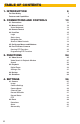
TABLE OF CONTENTS 1. INTRODUCTION 6 For Your Safety 7 Features and Capabilities 8 2. CONNECTIONS AND CONTROLS 10 2.1 Connections 11 2.2 Mouse Control Virtual Keyboard 13 13 2.3 Remote Control 14 2.4 Live View Login Status Icons Navigation Bar Shortcut Video Controls 15 15 17 17 18 2.5 On-Screen Menus and Windows 19 2.6 Pan-Tilt-Zoom Cameras Running PTZ Functions Programming PTZ Functions 21 22 22 3. FUNCTIONS 24 3.1 Video Search Video Search & Playback Window Search 25 25 26 3.
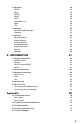
4.3 Network TCP/IP Ports PPPOE DDNS UPnP Block/Allow List Email FTP 48 48 49 49 49 50 50 50 51 4.4 Storage Hard Disk (HDD) Manager Grouping 52 52 53 4.5 System General Settings Display Settings Account Settings Auto Maintenance Import and Export Default Upgrade 54 54 56 57 58 59 60 60 5. INFORMATION 61 5.1 System Information Hard Disk Drive Record Bits Per Second (BPS) Version 62 62 63 63 63 5.2 Event Information 64 5.3 Network Information Online Users Load Test 65 65 65 66 5.
INTRODUCTION CHAPTER 1 Get to know your new system a little better. Subjects in this chapter: 6 Important safety warnings. 7 Product features.
FOR YOUR SAFETY To prevent damage to your Q-See product or injury to yourself or to others, read and understand the following safety precautions in their entirety before installing or using this equipment. Keep these safety instructions where all those who use the product will read them. WARNING! ELECTRIC SHOCK RISK! n Check the unit and any accessories included in the package immediately after opening. If items are missing or damaged, repackage and return to the point of purchase.
FEATURES AND CAPABILITIES Your Analog HD DVR (Digital Video Recorder) contains brand new technology with professional-grade features and flexibility that allows the do-it-yourselfer to easily setup and maintain a reliable and secure security system for home and office. It utilizes a dual-core CPU running an embedded Linux operating system to maintain stable operation and a popular H.
Multiple Backup Options A built-in USB port gives you the option of backing up and transferring your video footage using a flash drive or external USB hard drive. Files can also be accessed from your DVR system to a remote computer location by logging on remotely. Easily Connect to a VGA or HD Display This system comes with VGA and HDMI video output ports to allow you to connect to a computer monitor (19” or larger) or HD display for viewing purposes.
CONNECTIONS AND CONTROLS CHAPTER 2 This chapter covers the ports and connectors on your DVR along with providing an introduction to the onscreen controls and menus. Subjects in this chapter: 10 Identifying connectors on your DVR. 11 Using the mouse. 13 Using the remote control. 14 On-screen live viewing. 15 Watching multiple cameras at the same time. 15 Logging into your system. 15 Using the Shortcut Menu.
2.1 CONNECTIONS The illustrations below show the ports found on the back of your DVR. Their location will differ by model, but their function will be the same. The Connections and Specifications sheet that came with your recorder will show the layout of your recorder’s connectors along with any extra information that may apply to your model. DC 48V DC 48VDC 12V DC 12V RS232 POWER RS232 R Your DVR will have either a small port (top) or a larger, more conventional power port (below).
Depending on your model, your DVR may have one or more of these ports as well: RS232 RS232 This port is for factory maintenance only. RS232 AUDIO AUDIO IN Standard RCA-type connectors. Audio In ports are for connecting microphones which have been located near a camera to capture audio. The Audio Out port is to connect to a speaker. The color of these ports may vary. AUDIO IN VIDEO OUT VIDEO OUT VIDEO OUT (RCA) Connect to a standard television as a video display using an RCA cable (not included).
2.2 MOUSE CONTROL Your DVR is controlled through the USB mouse. Some models also include an infrared remote control and buttons on the front panel that serve as shortcuts. The mouse works the same as on a computer with different functions possible: LEFT CLICK: Selecting an item Opening a menu Checking a box or motion detection status Selecting letters, numbers or symbols on the virtual keyboard.
2.3 REMOTE CONTROL The buttons on the Remote Control operate in the same manner as on a conventional video player remote. Some buttons have multiple functions depending on which menu is being accessed. # Name Function 1 Power Button Turn on or shut down the DVR before turning it off with the power switch. 2 Address An additional security feature. You can require the DVR to ask you to enter the Device Number (found in the General Settings menu) before being able to access the log-in screen.
2.4 LIVE VIEW Live View is the default mode for your DVR. It will display the video feeds from your cameras - either a single channel, or from multiples. You do not need to be logged in to view or change channels. Single Screen 4 Screens 9 Screens 8 Screens 16 Screens PICTURE 2.4-1 The number of channels that can be displayed at once depends on the capacity of your DVR. For instance, if you have a four-channel system, the viewing options will be limited to single- or four-screen modes.
SHORTCUT MENU In Live View mode, right-clicking anywhere on the screen will bring up the pop-up Shortcut Menu Shortcut Menu. This menu allows you to quickly change your viewing mode as well as moving directly to a selection of menus, including the Main Menu. View - This allows you to view a group of cameras on screen at the same time. The number of cameras available will depend on how many cameras your DVR will support. The arrows to the right of the view options will allow you to select specific cameras.
STATUS ICONS There are four icons that will appear on the left side of each channel’s view. They provide a quick look at that camera’s status. Motion detected Recording NAVIGATION BAR When this is enabled in the General Settings menu, left-clicking on the Live View display will open the Navigation Bar allowing you shortcut access to select menus and functions. It also serves as an easy-toview status bar showing the current situation with alerts, network, and drives.
SHORTCUT VIDEO CONTROLS Moving the mouse to the upper center of a channel with a live feed will reveal the Shortcut Video Controls. These allow you to perform quick playback and backup functions, digitally zoom in and add another camera. 1 2 3 4 5 PICTURE 2.4-5 1 Realtime Playback 3 Quick Backup 2 Digital Zoom 4 Snapshot 5 Audio Realtime Playback - The window will play back the most recent segment of video recorded by that camera.
2.5 ON-SCREEN MENUS AND WINDOWS Your DVR will normally display live video from your cameras in the Live Viewing mode. It is configured to record video only when it detects movement - and for most people, this is sufficient. But, everyone’s needs are different so we’ve organized the on-screen menu in a way to make it easy for you to do what you want, quickly and easily. Right clicking with the mouse will bring up the Shortcut Menu which lets you access the Main Menu: PICTURE 2.
Search/ Playback FUNCTIONS Backup Shutdown System MAIN MENU Event INFO Network Online Users Load Test Log Camera Event SETTINGS Network Storage System 20 HDD Record BPS Version Remote Image Camera Settings Camera Name Recording Schedule Recording Status PTZ Detections Alarm Abnormality Alarm Out TCP/IP Block/Allow Ports Email PPPOE FTP DDNS POE Switch UPnP HDD Manage Grouping General Default Display Upgrade Account Auto Maintain Import/Export
2.6 PAN-TILT-ZOOM CAMERAS AnalogHD Pan-Tilt-Zoom (PTZ) cameras are plug-and-play like other AnalogHD cameras. Unlike conventional PTZ cameras, they don’t require additional wiring as control signals are sent through the same wire that carries the camera’s video. Because of their extra capabilities, they require additional setup to program their movements. These settings are found in the same window used to control the direction of the PTZ camera.
EXPANDED CONTROLS Clicking on the arrow at the far right of the PTZ Control window reveals the expanded controls area which lets you command the camera to run a pre-programmed function. PICTURE 2.6-4 Aux Controls additional features such as lamp or wipers. (If available) Menu Opens the camera’s internal on-screen menu (if available). Preset Point Moves camera to a pre-set point. Tour Camera will move to a sequence of pre-set points.
Tour This is also known as a “Patrol”. 1. Enter the number (1-8) for this Tour (Patrol). 2. Select the first Preset Point by entering its number. 3. Click Add Preset. 4. Enter additional points (up to 16) the same way). 5. Right-click to exit this window back to the PTZ Control window. PICTURE 2.6-6 Pattern The camera will record a pattern you create using the Directional Controls in real-time and will repeat it exactly when you run the pattern. 1. Enter the number (1-5) for this Pattern. 2.
FUNCTIONS CHAPTER 3 This chapter covers the most commonly used, day-today features which are found in the Functions area at the top of the menu. Subjects in this chapter: 24 The Video Search and Playback Window. 25 Searching for a recorded video. 26 Locking a file to prevent deletion. 27 Playing back recorded video. 28 Saving recorded video. 32 Back up some or all of your recorded videos. 32 Shut down the DVR.
3.1 VIDEO SEARCH VIDEO SEARCH & PLAYBACK WINDOW 1 From R/W HDD REC 2 < Su 1 8 15 22 29 3 Jan Mo 2 9 16 23 30 4 5 7 10 6 8 9 1 2 3 Stop 14 # 4 Sync 15 5 6 7 All Record 8 Normal 16 9 10 Alarm 11 12 0 14 15 16 17 18 Motion 19 20 24hr 17 Item 2014 We Th Fr 4 5 6 11 12 13 18 19 20 25 26 27 1 2 3 4 12 11 00: 00: 00 0 Tu 3 10 17 24 31 PIC 1 Interval > Sa 7 14 21 28 13 - 00: 00: 00 21 2hr 22 1hr PICTURE 3.
11 SEARCH Select recorded videos to play back, back up, or lock for later using the Search function. You can reach the Search and Playback window can be reached through either the Navigation Bar (left) or Shortcut Menu (right). From R/W HDD REC PIC 1 Interval PICTURE 3.1-2 PICTURE 3.1-3 < Su 1 8 15 22 29 STEP 1. The calendar in the upper right of the Video Search window will show dates containing recorded video in blue.
STEP 5. Once you have refined your search, click on the File Search (Picture 3.1-7) button to refresh your results. PICTURE 3.1-7 STEP 6. The DVR will produce a list of recorded events. The list will show start time and type of recording. M = Motion A = Alarm R = Regular • A box at the bottom of the list will show the start time, end time and file size of a selected video. STEP 7. Double-click on a file to begin playback. You can double click on another file in the list to switch to that video.
3.2 PLAYBACK Once you’ve selected your video(s), you can control the playback in the same manner as using a VCR or computer’s media playback software using the controls below the video screen. You can also play in reverse as well as forward, frame-by-frame movement and multiple playback speeds. Double-clicking on a screen in a multi-channel display format will switch to a single-channel display.
Video Playback Controls Play Play Forward Reverse Stop Slow/Fast Play Volume Control Frame Adv/Rev PICTURE 3.2-2 Start, Stop and Play Clicking either of the Play buttons will start the playback in the desired direction. The button’s icon will change to a Pause icon to allow you to freeze the playback as needed. If you have Sync unchecked, clicking Stop will end the playback of the video in the selected screen while any other videos will continue to play.
8 9 10 11 12 13 14 15 16 17 18 19 20 21 DIGITAL ZOOM Digital zoom in video playback operates22 differently than it24 does in25 Live View at the 23 26as described 27 28 beginning of this chapter. Both are digital zooms where the image is electronically enlarged - usually 29You 30 31enlarge an area of a video by clicking and in exchange for a decrease in image clarity. can digitally dragging with the cursor on the area of interest. This action will draw a green rectangle on the screen.
SAVING A FILE This process lets you back up the files you’ve selected. If you want to back up a lot of files, please see the next section. Once you have backed up these files to an external USB device they can be played back on a computer. You must have a USB device connected to the USB port on the front of the DVR before proceeding. 00 : 00 : 00 STEP 1. In your file list to the right of the playback screen, check the box next to the file(s) you wish to save.
3.3 BACKUP This DVR supports backing up files from the hard drive to both an external USB storage device as well as over a network. Network downloads are covered in the Remote Monitoring Guide. The Backup menu is located in the Functions section of the Main menu. PICTURE 3.3-1 The Backup window will display any connected devices along with available space and status. If you have a device connected to the USB port on the front of the DVR and it does not appear, press the Browse button.
Once you have selected the files, press Start to begin the download. A progress bar will be displayed showing estimated time remaining. During the download, the Start button will change to Stop. You can stop the process at any time by pressing the button again. You can also right-click out of the menu once the file transfer has begun to go on to other activities without cancelling the download. PICTURE 3.
3.4 SHUTDOWN The DVR should never be shut off by unplugging it or by using the power switch without first using the Shutdown function. This function allows you to shut down the DVR safely by letting the system finish writing files, parking the hard drive and other actions to preserve the electronics. Once the process has finished (generally a minute or two), the recorder will inform you that it can be safely unplugged or the power switch can be turned off. PICTURE 3.
TURN OFF STARTUP WIZARD Once the DVR is connected to the network and the Internet, there is no need to run the Startup Wizard again. If you did not turn it off at the end of the setup process, you may disable it. 1. Select System at the bottom of the Main Menu. 2. Make sure that the General submenu is selected. 2. Deselect Startup Wizard. 4. Click Save. PICTURE 3.4-2 PICTURE 3.
SETTINGS CHAPTER 4 Most users will make occasional changes to their system using the Settings area of the menu as they become more familiar with their system and how to optimize it to best suit their needs. Subjects in this chapter: 36 Configuring camera video. 38 Setting up a recording schedule. 40 Setting up a PTZ camera. 42 Setting up motion detection. 43 Other alarms. 45 Other network connection options. 47 Setting up email notifications. 49 Managing hard drives.
4.1 CAMERA Use the Camera menu to add cameras, adjust their video settings, set recording schedules and control Pan-Tilt-Zoom (PTZ) cameras. These options are found in submenus and tabs. IMAGE Use this submenu to adjust the video image for each camera. PICTURE 4.1-1 • Select the channel you wish to modify in Channel. Mirror - Image will be “backwards” Saturation, Brightness, Contrast, Sharpness sliders - manually adjust video image. Flip - Image will be upside down. Light - Lightens picture.
CAMERA SETTINGS This submenu has three tabs covering the video stream (data transmission), on-screen displays of information and event notice snapshots. Resolution Tab PICTURE 4.1-2 Network download speeds can affect the amount of data that can be transferred. Your DVR records a larger “Main Stream” and a smaller, lower resolution “Extra Stream” which is accessed by remote devices. If you have enough bandwidth, you can remotely access the Main Stream for a clearer picture.
Overlay Tab This window has controls for on-screen displays from the camera as well as for masking sensitive areas. Cover Area - You can mask on-screen areas for privacy by clicking the Preview or Monitor button. • Preview hides areas on the DVR screen. • Monitor hides areas on mobile devices or computers that are logged in. • Up to four areas each can be set. • Clicking the Preview or Monitor box will reveal four buttons, to allow you to turn the boxes on or off.
CAMERA NAME Naming your cameras to something more descriptive may help you or other users quickly identify the area in view. PICTURE 4.1-6 CHANNEL TYPE The default method for connecting cameras to your DVR is to use coaxial camera cables. Users can also take advantage of a building’s pre-installed CAT5 network cables to connect to their cameras. • If CAT5 cables are used, then UTP must be selected for that channel. • Video baluns must be used on both ends of the cable.
RECORD SCHEDULE Your DVR comes from the factory set up to record whenever motion is detected. If you need to modify this schedule, this is where to do it. PICTURE 4.1-8 Eraser Clears the selected type of recording from that day Settings For precision scheduling Regular DVR will record constantly Motion Detection DVR will record when motion is detected Alarm DVR records when alarm triggers (DVRs with alarm inputs only).
Setting a Recording Schedule There are two ways to set up your schedule - either sheduling blocks of time using the timeline, or by setting precise start and stop times in the Period window. Pre-Record - The DVR can record the scene up to 30 seconds before motion is detected. Redundancy - If you have multiple hard drives, you can save the recording to both drives. Multi-Day Schedule - Click on the boxes to the left of the day names to link them and set the same schedule for all of those days.
RECORD STATUS This window offers a quick way to override the current camera settings should the need arise. • This window can also be reached by selecting Override in the Shortcut Menu. PICTURE 4.1-10 PTZ This is for use when connecting legacy pan-tilt platforms that use RS485 control wires. Your DVR must have a green RS485 block located on the back panel for local control or a similar connection where a remote camera is located.
4.2 EVENT Now that you’ve set up the recording schedule, you can use the Event window to direct the actions that the DVR will take when motion, tampering or loss of video is detected. PICTURE 4.2-1 DETECTIONS Motion Events This tab is divided into two parts. The upper portion is for fine-tuning the motion sensitivity of each camera while the lower segment controls how the DVR will respond when it detects motion on that channel.
The lower portion of the Motion Events window lets you control how the DVR will react when it detects motion. Trigger Period - Just as you’ve configured the DVR to record on a schedule, you can set the alert notifications to occur only at certain times. EXAMPLE: Turning off motion alerts during business hours when employees are in the building. Hold Time - This is the time, in seconds, that the DVR will wait after detecting motion before saving the file.
ALARM This window handles inputs from external alarms and sensors in the same way that the Detections window handles camera inputs. If your DVR does not have an alarm block, this feature will not appear in your menu. RS232 AUDIO IN VIDEO OUT PICTURE 4.2-5 Local Alarm This tab handles input from alarms connected directly to an alarm port on the back of the DVR, if your DVR has an alarm block. An illustrated example of an alarm block is shown in Picture 4.2-6. PICTURE 4.
ABNORMALITY If the DVR experiences an error with its hard disk drive (HDD) or its network connection, it can alert you to the problem so it can be quickly fixed. Disk Hard drive failure (or removal), disk errors or a full hard drive all can trigger a customizable set of alarms. PICTURE 4.2-8 Network Loss of network connection, and local network conflicts involving IP and MAC addresses, will prevent remote monitoring.
4.3 NETWORK The network settings control how the DVR communicates with your local network, and the Internet. For most users, following the instructions in the Setup Wizard will establish a reliable connection for remotely monitoring your system. The Remote Monitoring Setup poster provides instructions for more complex network connections. This section will cover the most important settings found in this window.
PORTS Ports are the “doorways” through which data travels to and from the DVR. Max Connection - Your DVR will support up to 20 remote connections. You can reduce this number if desired. TCP Port, HTTP Port - If you are experiencing problems with connecting your DVR to the Internet, it is likely because there are other devices on your network that use one of these two port numbers. Check the Remote Monitoring Setup poster or Remote Monitoring Guide for instructions on how to correct the situation.
UPNP Universal Plug ‘n Play is a technology that allows devices to discover each other on a network, which simplifies the process of adding your DVR to your network. Status - Shows whether your DVR is successfully connected to your network via UPnP. • UPnP is enabled on your DVR by default. • AT&T’s 2Wire brand routers do not support UPnP and you will have to forward ports 85 and 37777 according to the instructions on the Remote Monitoring Setup poster. PICTURE 4.
Interval – This adjusts the amount of time that will pass before the DVR sends out another e-mail. The interval can be set from 0 minutes to 6 hours (360 minutes). If you are getting too many e-mails, you may wish to increase the length of the interval. Health – When checked, the DVR will send out a test message at the interval below. Interval - The Health check interval can be up to 24 hours. • Once you’ve set up your email, click the Test button to check your settings.
4.4 STORAGE This window helps you manage your DVR’s internal hard drive(s). PICTURE 4.4-1 HARD DISK (HDD) MANAGER This window shows the status of your hard drives, including free space, and allows you to (re)format them if needed. • An installed and functioning hard drive will be represented by a line (-). • A missing hard drive will be represented by an empty circle ( ). • You can switch the status of a drive between Read/Write and Read Only if needed to preserve records.
GROUPING On systems with more than one internal hard drive, you can group multiple hard drives into a group that will act as a larger, single hard drive and different types of recordings can be assigned to that group. PICTURE 4.4-2 HDD (Hard Disk Drive) This is the tab where you assign drives to a group. Main Stream • The Main Stream video is the larger data stream used by the DVR and viewed when you play back the video at the DVR. • Use this tab to assign specific channels to the desired disk group.
4.5 SYSTEM Settings in this menu control the basic operations of the DVR itself. Among the other options, you can make changes to settings you made when you first set up your system. PICTURE 4.5-1 GENERAL SETTINGS General Device ID –Your name for your recorder. Device No. – If you are controlling more than one DVR with a single remote, this allows you to give each DVR a separate numerical ID. Language – QC DVRs can or will support English, Spanish or French.
Date & Time As the name implies, this window is for setting the date and time on your system. This is important to ensure the ability to use your recordings as evidence. Date Format – Choose your prefered format. Time Format – AM/PM or 24-Hour format. Date Separator – Period, dash or slash. System Time/Time Zone – Set the current date, time and time zone. Click Save. Daylight Savings Time – Set the date or week of the month that DST starts and ends for your area. If you do not have DST, uncheck the box.
DISPLAY SETTINGS This window lets you control your on-screen display. PICTURE 4.5-5 General Resolution – Adjust the screen resolution to match your monitor’s capabilities. Transparency – You can make your on-screen menus more transparent to let you see more of the video image behind them. Time Display/Channel Display – You can turn off these on-screen displays if desired. Image Enhance – Enabling this feature will allow the DVR to adjust the on-screen video image for clarity and color balance.
ACCOUNT SETTINGS This is the account management window where you can add and remove users as well as change user settings and permissions. PICTURE 4.5-7 • There are two user accounts which cannot be deleted: Admin and User. • You should change their passwords from their defaults: Admin: admin User: user Adding a New User • There are two types of accounts - Admin and User. • Admin accounts can control 15 different functions while User accounts can access up to 5. 1.
AUTO MAINTENANCE Just like your computer, the DVR can benefit from being restarted. This allows it to clear the memory and other temporary files that may slow it down. None of your settings will be deleted. PICTURE 4.5-9 Auto Reboot • Select the frequency (daily or weekly) that you want the system to reboot. • Select the time you want the reboot to occur. • The reboot process will take a few minutes. NOTE! You should set the reboot to take place on a date and time when it won’t interrupt recording.
IMPORT AND EXPORT If you are using more than one QC DVR, you can copy the settings from one machine to the other. PICTURE 4.5-10 • When you insert a USB drive into the front port of the DVR, you will be presented with a window with several options. Right-click to close this window. • Once a USB drive is connected, the Device Name, Total and Free Space windows will fill with information about that drive. • The file window operates like that on a Windows PC.
DEFAULT Restore some or all of your system’s factory settings. IMPORTANT! Restoring the default settings will remove any changes you’ve made to your recording schedules. PICTURE 4.5-11 UPGRADE Q-See is committed to improving our products. If you have registered your system with Q-See, you will receive notification of any product improvements. This includes firmware updates that can be downloaded from Q-See.
INFORMATION CHAPTER 5 The Information section gives you easy access to information about your DVR’s status. These windows are read-only as changes are made in the Settings section. Subjects in this chapter: Hard drive status. 61 Blocking online users. 64 Testing network connections. 65 Activity log. 66 Adding additional mobile devices to QC View. 67 Logging into Q-See’s QCView with a computer.
5.1 SYSTEM INFORMATION Get information on the status and health of your hard drive(s) as well as the data load on your system and network connection. PICTURE 5.1-1 HARD DISK DRIVE This window shows all of the drives installed in your DVR along with the drive status (Read/Write or Read Only), the size of the drive and how much free space is available. It also shows whether the drive is operating normally. S.M.A.R.T. Info Clicking on the hard disk icon to the far right of a drive’s name in the S.M.A.R.
RECORD This window shows the date and time of the first and last recordings on a hard drive. PICTURE 5.1-3 BITS PER SECOND (BPS) When this window is opened, green traces will show the data load for each channel in real time. • 1080p cameras will create a higher data load than 720p cameras • The current data load - in Kilobits Per Second will be shown as well. • This data can help identify network bandwidth issues. PICTURE 5.
5.2 EVENT INFORMATION This window shows the active event status of your DVR and connected cameras. PICTURE 5.2-1 • Items will be grayed out unless there is an event currently taking place, such as movement seen on one channel, or the loss of connection to the network.
5.3 NETWORK INFORMATION This is one of the “active” windows in the Information section. Here, you can see who is logged into your DVR as well as see and test the data transmission from your DVR. PICTURE 5.3-1 ONLINE USERS This shows remote users currently logged into your system. • Admin Accounts (Section 4.5) can disconnect a user. • Users can be blocked for up to 18 hours. LOAD You can see the status of your DVR’s network connection.
TEST You can see the status of your DVR’s connection to remote cameras and save the results for analysis. This is useful if you are experiencing problems receiving video. 1. Enter the camera’s network address found in the Camera > Remote Window (Picture 5.3-4) (see Section 4.1) into the Destination IP field. 2. Click Test. 3. Messages regarding the test will appear below the Destination IP field. PICTURE 5.
5.4 ACTIVITY LOG This searchable window contains the list of all user and system activities such as reboots, time updates and etc. PICTURE 5.4-1 • You can search for events by selecting a start and end time for the period to be searched • The search can be refined by selecting the typ of event you are searching for - motion, alarm, etc. • Clicking the icons under detail will show more information about the particular event, if available. • You can save your search results to a USB drive. It will be a .
5.5 SCAN N’ VIEW You used the Scan N’ View feature to connect your DVR to the Internet, your mobile devices and your network. You can easily connect with more phones, tablets and computers through the QR Code window. PICTURE 5.5-1 CONNECTING WITH MOBILE DEVICES You can easily add additional phones or tablets: 1. Download the QCView (phone) or QCViewHD (tablet) app from Google Play or the iTunes AppStore. 2. Launch the app. 3. Click on the “+” in the upper right. 4.
Appendix This section contains additional instructions for specific tasks and troubleshooting.
A.1 CONNECTING ALARMS Setting up alarm notifications is covered in Section 4.2 in this manual. This section covers how to connect alarms to your DVR. If your DVR features connections for external alarms – both input and output, then it can notify local users or send notification to a monitoring service when an event is detected. At the same time, the system can accept signals from motion detectors, smoke detectors or other alarms and begin recording based on that input and your settings.
The alarm output port should not be directly connected to a higher power load (greater than 1A) to avoid high current which may damage the relay. Use the co-contactor to establish the connection between the alarm output port and the load. • 2 way relay alarm output (NO contact). Provides external power to external alarm device. • To avoid overloading, please read the following relay parameters sheet carefully. • RS485 A/B cable is for the A/B cable of the PTZ camera.
A.2 HARD DRIVE INSTALLATION/REMOVAL • Your DVR uses one or more standard computer A/V-rated SATA (Serial Advanced Technology Attachment) hard disk drive and will support up to a 4TB (terabytes) drive. • These drives are the current industry standard and may be purchased wherever computer parts are sold. It is strongly advised against opening the case when atmospheric conditions present the risk of static discharge which can damage electronic components.
A/V RATED HARD DRIVE PICTURE A.2-4 PICTURE A.2-3 STEP 4. Line up hard drive mounting screws with mounting holes at the bottom of the DVR and slide the hard drive to move the screws to the narrow part of the holes. STEP 5. Carefully turn DVR over. Hold onto the hard drive to keep it from sliding out. HARD DRIVE DATA CABLE PICTURE A.2-5 POWER CABLE PICTURE A.2-6 STEP 6. Make sure that the mounting screws are in the narrow part of the holes and tighten them firmly. STEP 7.
A.3 TROUBLESHOOTING 1. a. b. c. d. e. The DVR does not boot up properly Possible Causes: Input power is not correct - check power supply. Power switch button is damaged. Updated firmware using wrong file. Hard drive malfunction or something wrong with hard drive cable. Main board is damaged. a. b. c. d. e. DVR often automatically shuts down or stops running. Possible Causes: Input voltage is not stable or it is too low. Hard drive malfunction or something is wrong with the cable.
8. There is no audio when monitoring. Possible Causes: a. Channel with audio is not full screen, make the channel you want to hear audio on full screen. b. Audio cable is damaged. c. No speaker or damaged speaker. d. Low volume. e. No microphone. 9. There is audio when monitoring but there is no audio when system plays back. Possible Causes: a. Setup is not correct. Please enable audio function b. Corresponding channel has no audio input. 10. Time display is not correct. Possible Causes: a.
16. Remote control does not work. Possible Causes: a. Need to enter the correct Device ID on the remote control. b. Distance over 6 feet. c. Remote control battery power is low. d. Remote control is damaged or DVR front panel is damaged. 17. Can not playback the downloaded file. Possible Causes: a. There is no media player. b. Need Divx Codec in file player 18. Forgot DVR password. a. Contact Q-See tech support and we can generate a new password for the unit.
A.4 Q-SEE PRODUCT WARRANTY 2-year Limited Warranty Thank you for choosing Q-See to provide for your security needs, and welcome to the Q-See community! We stand behind the quality of all of our products, and we want you to know that we’re here to help you should you ever need assistance with your Q-See purchase. To receive full warranty benefits and lightning fast support, register your products at www.Q-See.com.