
Technical Manual


8 9
PICTURE 1-4
ESC
21 3
54 6
87 9
-/--C 0
DISP
RUN
SHOT CAM
SPEED AUTO
PRESET
HOME
SETUP
PATTERN
A
DELETE
B
S1
F1
S2
F2
S3
F3
S4
F4
P1
P5
P2
P6
P3
P7
P4
P8
OPEN
CLOSE
IRIS
FOCUS+
FOCUS-
ZOOM+
ZOOM-
ENTER
1 6
2
7
3
4
11
5
12
14
16
20
21
13
15
23
9
17
18
19
10
8
22
24
25
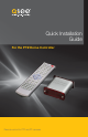
1.2 REMOTE CONTROL
All of the commands and settings for your PTZ camera will be made using the remote that came with
your camera. If you are connecting your camera to a DVR, the remote that came with that system will
not work for controlling your camera.
# Button Function
1 Escape Goes to address input mode
2 Display Shows current settings
3 Preset Press to create a preset point
4 Run Run surveillance pattern
5
Home Directs camera back to “home”
point
6 Setup Press to change baud rate
7 Delete Clear preset point
8 Pattern Create surveillance pattern
9 B Mark start and end points for
auto pan function
10 A
11 Numbers Enter numbers
12 Clear Clears number entry
13
Multi-digit Press before entering numbers
with two or more digits
14 Shot Press to go to preset point
15
Directional
Controls
Moves the camera to desired
position
16
Speed Press and then enter desired
speed (2-63)
17
Cam Press to change camera
address
18 Enter Confirm selection/action
19
Auto Spins camera 360° from home
point
20
Focus Camera automatically adjusts
focus and light level. These are
not usable with your camera.
21
Iris
22 Zoom Zoom in or out
23
Speed
Shortcuts
Increase or decrease speed.
S1=8, S2=40, S3=51, S4=63
24
Focus
Shortcuts
Not usable with this camera
25
Preset
Shortcuts
Moves camera directly to preset
points 1-8
OPERATION
CHAPTER 2
2.1 SETTING ADDRESS AND PROTOCOL
It is possible to connect multiple PTZ cameras to the Control Module using the RS485 block on the
back. However, each camera will need to have a distinct address - from 1 to 16 - in order to ensure
that commands are being issued to the correct camera. In addition, both camera and Control Module
must use the same communication protocol in order to interact. Both the camera and the Control
Module can use the Pelco-D or Pelco-P protocols. The speed of this communication, called the baud
rate, is also important as a lower communication speed allows control of the camera over longer
distances. It should be noted, however, that in most applications a higher speed isn’t a major factor.
Each attached camera can use a different protocol and baud rate, if desired.
Your camera is set by default to an address of 1, with a baud rate of 2400 using the Pelco-D protocol.
You should not need to change this except in unique circumstances, such as multiple cameras
connected to a single Control Module.
If you need to change the default settings, you must do so both in the camera and on the Control
Module. In the camera, they are made using DIP switches as covered in the Setting Baud Rate
and Address section of the User Manual that came with your camera.
For the Control Module, these settings need to be changed to match those in the camera using the
remote.
SETTING BAUD RATE AND PROTOCOL
Press the DISP button to show the current baud settings. Please note that you may have to push
DISP multiple times to cycle through the various settings (speed, firmware version, etc.) to reach the
baud settings. If the Control Module is set to the factory default, it will read d=24 meaning that it is
set to use the Pelco-D protocol at 2400 bits per second (bps).
To change baud rate and protocol
PICTURE 2-1
STEP 1. Press and hold the Setup button
for 3 seconds until you see the current
baud rate settings, such as d=24
STEP 2. Press the up or down arrow key to
switch between Pelco-D (d) and Pelco-P
(P) protocols.
STEP 3. Use the left and right arrow keys to change the baud rate between 12/24/48/96.
STEP 4. Press Enter to save your setting.
Pressing and holding C while in the baud rate mode will blank the LED readout for 10 seconds and
reset the Control Module back to Pelco-D at 2400bps.