
Technical Manual


8
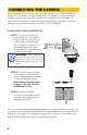
STEP 1.ConnecttheBNCand
power leads from the camera
to the matching connectors on
a video/power siamese cable
(Note: these may need to be
purchased separately if your
camera was not included as part
of a bundle package).
STEP 2.Connectthepowerlead
on the other end of the video/
power cable to a power adapter
or power distribution panel.
Make certain that the power
supply is rated for 12 volts
and 800mA to 1.5A.
STEP 3.ConnecttheBNC
connector on that same end of
the cable to a Video In port on
the back of the DVR.
CONNECTING THE CAMERA
Before you can operate the camera, you must connect it to a system which can
support PTZ operations. There are three sets of connectors - power, video and
the bare control wires. This latter connection is covered on the next page. We
recommend connecting the camera (at least temporarily) to the DVR to test your
settings and connections before mounting it in its final location.
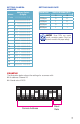
AUDIO IN VIDEO IN
1 3
2 4
1 3
2 4
POWER AND VIDEO CONNECTION
IMPORTANT!
When connecting the
power and video cable between the camera
and the DVR, the “male” power end (red plug)
connects to the matching power lead on the
camera.
You can now plug the camera’s power adapter into a surge protector and turn it on.
To protect your investment, we STRONGLY recommended using a surge protector
thatisUL-1449rated,foraclampingvoltageof330orlower,aJouleratingofat
least 400 and a response time of 10 nanoseconds or less.