
Technical Manual


9
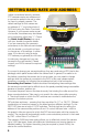
PTZ CONTROL CONNECTION
In addition to connecting the power and video leads to the camera, you must also
connect the two control wire leads to the RS485 ports in the alarm block on the
back of the DVR. These blocks can vary in layout as shown below, but the ports
used by your DVR are generally labelled “RS485”, “RS422”, “PTZ” or “P/Z”.
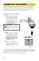
As seen in the picture on the right, the wire leads from the
camera are two different colors and are labeled. They are
also pre-installed into a block which plugs into a matching
receptacle on the extension cable. There are matching wire
leads (see inset) at the other end of the extension cable
which must be inserted into the ports on the back of the
DVR. In the case of the RS485 ports being marked as
positive (+) and negative (-), the wire designated RS485A
(orange tip) is the positive lead while the wire marked
RS485B (yellow tip) is to go into the negative port. PTZ
blocks on your DVR either have small screws to above
each port to secure the wire or require a lock above the
port to be depressed with an object like a small screw
driver in order to fully insert the wire. In the latter, when the
lock is released, an internal clamp will keep the wire firmly
secured in the port. If the wire can easily be removed from
the port, then it isn’t secure and you can experience control
difficulties until it is properly attached.
Serial PortSerial Port AdvancedAdvanced
P.T.ZP.T.Z
DefaultDefault
ApplyApply ExitExit
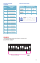
CH Enable Address Baud Rate Protocol Simulative Cruise
1
2
3
4
CH Enable Address Baud Rate Protocol Simulative Cruise
1
2
3
4
AllAll
11
22
33
44
24002400
96009600
96009600
96009600
PELCODPELCOD
PELCOPPELCOP
PELCOPPELCOP
PELCOPPELCOP
96009600 PELCOPPELCOP
Some examples of PTZ blocks. One using screws (left) and two using spring-loaded locks.
To connect your camera to the DVR
over a distance, you will need to use
both a video/power cable and a pair of
24-gauge wires to connect to the alarm
block. If your camera came as part of a
package, these wires may be included
separately or as part of the video and
power cable.
Space permitting, multiple PTZ cameras may be connected to the same ports.
They will each require a different address which is set up using the DIP switches as
covered in the previous section.
Once you have made your connections, you will need to make settings on the DVR
in order to control it. You will need to consult your DVR’s manual for this procedure,
but a sample screen (from a Q-See QT-series DVR) is shown on the right.