
Installation Guide


5
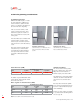
Flange body - concrete floor
Showerchannel length(l)
plus 2” (50mm)
Max width
12” (300mm)
Width at end
9” (225mm)
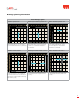
Showerchannel length(l)
plus 2” (50mm)
Max width
12” (300mm)
Width at end
9” (225mm)
Showerchannel length(l)
plus 2” (50mm)
Max width
12” (300mm)
Width at end
9” (225mm)
1.
2.
3.
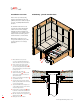
Box out detail showing suggested
dimensions
After removing box form work
connect shower channel to plumbing
pipe work using stainless steel
connector part number 93874.
Shower channel fitted in place prior
to final concrete slurry pour. Shower
channel flange should be at same
level as original concrete slab.
G
G
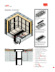
1. Frame out shower surround in concrete slab
as required, see diagram top right.
2. Set top edge of shower channel slightly
below finished tile level, cut plastic installation
feet to height to hold shower channel at
required height and level.
3. Connect outlet to pipe work using 2“
stainless coupler.
4. Pour concrete slurry into framed out
void in concrete slab to height of flange on
channel body.
5. Install ‘hot-mop’/liquid membrane, fully
covering concrete and flange of shower
channel in accordance with manufacturer‘s
instructions.
6. Trowel mortar to required height and grade,
approx. 1%.
7. Apply thin set.
8. Lay tile and grout.
9. Install grate into shower channel.
G