
- Two Channel Low Profile RS-232 Asynchronous Communications Adapter User Manual


2 Hardware Configuration
The DSCLP-100 is automatically configured at boot time by the computer's
BIOS or operating system. There are no required switches or jumpers to set for
installation.
This chapter lists a number of optional jumper settings that control various
hardware features. Jumpers J2, J4-J5 are grouped together at the end of the board
opposite the HD-44 connector. Any changes from the factory default should be made
before installing the DSCLP-100 in the computer.
2.1 Factory Default Configuration
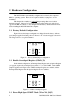
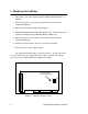
Figure 2 shows the jumper configuration as shipped from the factory, with two
spare jumpers applied in neutral positions. Remove one or both and apply as shown in
following sections to set optional features.
SPAD
X2
X4
J2
J4
J5
Figure 2 --- Factory default jumper configuration
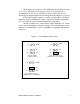
2.2 Enable Scratchpad Register (SPAD, J2)
In the default configuration, an Interrupt Status Register and an Options Register
(see page 0) replace the scratchpad (base address + 7) of each UART. If the SPAD
jumper is applied as in Figure 3, the UART scratchpad registers are enabled, and the
Interrupt Status Register and the Options Register are not available.
SPAD
X2
X4
J2
J4
J5
Figure 3 --- Enable scratchpad registers
2.3 Force High-Speed UART Clock (X2 or X4, J4-J5)
2 DSCLP/SSCLP-100 User's Manual