
Asynchronous Communications Adapter User's Manual RS-232


3 Hardware Installation
1. Turn off the power of the computer system in which the
ESC(LP)-100 is to be installed.
2. Remove the system cover according to the instructions provided by
the computer manufacturer.
3. Install the ESC(LP)-100 in any empty PCI expansion slot. The board
should be secured by installing the Option Retaining Bracket (ORB)
screw.
4. Replace the system cover according to the instructions provided by
the computer manufacturer.
5. Attach and secure the cable connectors to the desired equipment.
6. Turn on the power of the computer system.
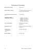
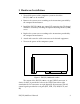
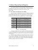
Figure 1: ESC(LP)-100 board outline
The output of the ESC(LP)-100 is a 68-pin VHDCI connector. A
choice of cables is provided to convert the VHDCI into either eight
standard male D-9 connectors or eight 10-pin RJ-45 connectors with all
control signals provided to each port (RTS, DTR, CTS, DSR, DCD, and
RI).
ESC(LP)-100 User's Manual 3