GV300CAU Series User Manual GV300CAU Series User Manual GSM/GPRS/WCDMA/LTE Cat1/GNSS Tracker QSZTRACGV300CUM0101 Version: 1.
GV300CAU Series User Manual Document Title GV300CAU Series User Manual Version 1.01 Date 2020-09-02 Status Released Document Control ID QSZTRACGV300CUM0101 General Notes Queclink offers this information as a service to its customers, to support application and engineering efforts that use the products designed by Queclink. The information provided is based upon requirements specifically provided to Queclink by the customers.
GV300CAU Series User Manual Contents 0. Revision History ............................................................................................................................. 1 1. Introduction .................................................................................................................................. 2 1.1. GV300CAU Series Products ...................................................................................................... 2 1.2. Reference............................
GV300CAU Series User Manual 0. Revision History Version Date Author Description of Change 1.00 2020-06-20 Arry Wang Initial 1.
GV300CAU Series User Manual 1. Introduction The GV300CAU Series are compact GPS trackers designed for a wide variety of vehicle tracking applications. It has multiple I/O interfaces that can be used for monitoring or controlling external devices. The GV300CAU Series supports various bands of LTE CAT1/ WCDMA/GSM used by Latin America and Middle East cellular operators. The built-in GPS receiver has superior sensitivity and fast initial positioning.
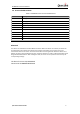
GV300CAU Series User Manual 1.3. Terms and Abbreviations Table 3. GV300CAU Series Terms and Abbreviations Abbreviation Description AGND Analog Ground AIN Analog Input DIN Digital Input DOUT Digital Output GND Ground MIC Microphone RXD Receive Data TXD Transmit Data SPKN Speaker Negative SPKP Speaker Positive Bluetooth The device role of Bluetooth could be Master and Slave.
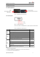
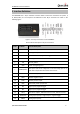
GV300CAU Series User Manual 2. Product Overview 2.1. Product Appearance LEDs Internal Battery Switch 16-pin Connector External GPS Antenna Connector USB Interface Figure 1. GV300CAU Series Products View 2.2. LED Description Figure 2. GV300CAU Series LEDs There are three LEDs on GV300CAU Series. For details, please see the table below. Table 4. GV300CAU Series LED Description LED CEL (Note 1) GPS (Note 2) PWR (Note 2) Device Status LED Status Device is searching CEL network.
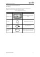
GV300CAU Series User Manual 4. Slow flashing: About 200ms ON/1000ms OFF 2.3. Parts List Before starting, check whether all the following items have been included with your GV300CAU. If anything is missing, please contact your supplier. Table 5.
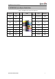
GV300CAU Series User Manual 3. Interface Definition The GV300CAU has a 16-pin interface connector which contains the connections for power, I/ O, RS232, MIC, etc. The sequence and definition of the 16-pin connector are shown in the following figure: Figure 3. The 16-pin Connector on the GV300CAU Series Table 6. Description of 16-pin Connections Pin No.
GV300CAU Series User Manual 4. GV300CAU Series Device Cable Color Table 7. GV300CAU Series Cable Color Definition Definition Color PIN No. OUT2 Yellow 8 ADIN3/OUT3 Brown GND PIN No.
GV300CAU Series User Manual 5. Getting Started 5.1. Opening and Closing the Case Figure 4. Opening and Closing the Case To open: Insert the opener into the gap of the case as shown above, and push the opener up until the case is unsnapped. To close: Place the cover on the bottom at the position as shown above. Slide the cover against the direction of the arrow until it snaps. 5.2.
GV300CAU Series User Manual 5.3. Installing the Internal Backup Battery GV300CAU has an internal backup Li-ion battery. Figure 6. Backup Battery Installation 5.4. Switching on the Backup Battery To use the GV300CAU Series backup battery, the switch must be at the ON position. The switch and the ON/OFF position are shown as below. Internal Battery Switch Figure 7. Switch and ON/OFF Position Note: 1. The switch must beat the “OFF” position when the GV300CAU series is shipped on an aircraft. 2.
GV300CAU Series User Manual 5.6. Power Supply Connection PWR (pin 11)/GND (pin 6) are the power input pins. The input voltage range for this device is from 8V to 32V. The device is designed to be installed in vehicles that operate on 12V or 24V systems without the need for external transformers. Figure 9. Typical Power Connection 5.7. Ignition Detection IGN (pin 3) is used for ignition detection. It is recommended to connect this pin to the “RUN” position of the vehicle ignition switch as shown below.
GV300CAU Series User Manual The following picture shows the recommended connection of a digital input. Figure 11. Digital Input Connection 5.9. Analog Input/Digital Output This is a special I/O can be configured as a 0-32V analog input or an open drain output with 150mA max drive current. Figure 12. Analog Input or Digital out Connection 5.10. Digital Outputs There are three digital outputs on GV300CAU. All are of open drain type and the maximum drain current is 150 mA.
GV300CAU Series User Manual Figure 14. Typical Connection with a Relay Figure 15. Typical Connection with a LED Note: OUT1 will latch the output state during reset. Warning: Many modern relays come with a flyback diode pre-installed internal to the relay itself. If the relay has this diode, insure the relay polarity connected is properly used. If this diode is not internal, it should be added externally. A common diode such as a 1N4004 will work in most circumstances.
GV300CAU Series User Manual 5.11. Serial Port/UART Interface There are two lines dedicated to the Serial Port/UART interface (TXD/RXD). TXD/RXD is standard RS232 signal. Figure 16.
GV300CAU Series User Manual 6. Installation Precautions Firmly install the device to a reliable surface to prevent falling off. Make the side with antenna face sky to have better signal reception. Do not install the device under metal surface or in enclosed environments having difficulty in getting GPS and network signal.
GV300CAU Series User Manual 7. Troubleshooting and Safety Info 7.1. Troubleshooting Table 11. GV300CAU Series Troubleshooting List Problem Possible Reason Solution After the device is turned on, the CEL LED always flashes quickly. The signal is too weak. The device isn’t registered to the network. Move the device to a place with good network coverage. APN is not right. Ask the network operator for the right APN. The IP address or port of the backend server is wrong.
GV300CAU Series User Manual 8.
FCC Statement: Any Changes or modifications not expressly approved by the party responsible for compliance could void the user’s authority to operate the equipment. This device complies with part 15 of the FCC Rules. Operation is subject to the following two conditions: (1) This device may not cause harmful interference,and (2) this device must accept any interference received, including interference that may cause undesired operation.