QT and QTS Series Compressors Instruction Manual This manual contains important safety information and must be carefully read in its entirety and understood prior to installation by all personnel who install, operate and/or maintain this product. On-line product registration, parts ordering and warranty information is available at www.quincycompressor.com Manual No.
WARRANTY Quincy Compressor® Reciprocating Products QT® & QP® Series Compressors GENERAL PROVISIONS Quincy Compressor (The Seller) warrants to each retail purchaser (Purchaser) products of the Seller’s own manufacture against defects in material and workmanship. With respect to products not manufactured by the Seller, the Seller will, if practical, pass along the warranty of the original manufacturer.
WARRANTY Quincy Compressor® Reciprocating Products QTS® Single Stage Compressors GENERAL PROVISIONS Quincy Compressor (the Company) warrants the compressor to be free from defects in materials and workmanship for a period of twelve (12) months from date of purchase (proof of purchase date required). If proof of purchase date is not available, warranty coverage begins on date of shipment from the factory.
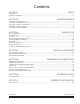
Contents SECTION 1 SAFETY SECTION 2 SYSTEM DYNAMICS SECTION 3 INSTALLATION SECTION 4 START-UP & OPERATION SECTION 5 MAINTENANCE & LUBRICATION SECTION 6 TROUBLESHOOTING SECTION 7 REFERENCE INFORMATION Safety First.............................................................................................................................................................2 Summary of Changes.............................................................................................................
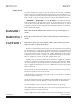
SECTION 1 SAFETY Safety First At Quincy Compressor safety is not only a primary concern, but a faithfully performed practice. Beginning with the design stage, safety is built into every Quincy compressor. It is the intention of this manual to pass along the “safety first” concept to you by providing safety precautions throughout its pages. “DANGER !”, “WARNING !”, and “CAUTION !” are displayed in large bold capital letters in the left hand column to call attention to areas of vital concern.
cedures. Some surface temperatures exceed 350°F when the compressor is operating. •Do not operate the unit with any of its safety guards, shields, screens, enclosure panels or doors removed. •Do not remove or paint over any DANGER!, WARNING!, CAUTION!, or instructional materials attached to the compressor. Lack of information regarding hazardous conditions can cause property damage or personal injury. •Periodically check all pressure relief valves for proper operation.
WARNING ! Oil and moisture residue must be drained from the air receiver daily or after each use. Accumulations of oil residue in the receiver can be ignited by embers of carbon created by the heat of compression, causing an explosion, damage to property and injury to personnel. CAUTION ! When using battery cables to start engine driven units do not use more than a total of 40 ft. of #4 gauge cable (GND & HOT).
SECTION 2 SYSTEM DYNAMICS Description & Application QT Series compressors are heavy duty, splash lubricated, air cooled, belt driven compressors capable of delivering 175 PSIG of compressed air. QTS Series single stage compressors (capable of delivering 125 PSIG of compressed air) and vacuum pumps are air-cooled and splash lubricated. See appropriate parts manual for recommended RPM operating range and pressure. The QTS-3VAC & QTS-5VAC vacuum pumps are approved for sweet dry natural gas applications.
Principles of Cooling Systems These compressors are equipped with a compressor sheave with fan blades. The fan blades force ambient air across cylinder head and intercooler fins to cool the compressor. These compressors are designed to be operated with the compressor sheave turning in a counterclockwise rotation (as viewed “tummy to the sheave”). Principles of Dryers & Filters Moisture occurs naturally in air lines as a result of compression.
SECTION 3 INSTALLATION Receiving Delivery Immediately upon receipt of compressor equipment and prior to completely uncrating, the following steps should be taken: WARNING ! Step 1) Inspect compressor equipment for damage that may have occurred during shipment. If any damage is found, demand an inspection from the carrier. Ask the carrier how to file a claim for shipping damages. (Refer to SECTION 3, Freight Damage for complete details.) Shipping damage is not covered by Quincy Compressor warranty.
ment at the premises where the delivery was made. Do not move the damaged freight from the premises where the original delivery was made. Retain all containers and packing for inspection by the carrier. A claim form can be requested from the carrier: Standard Form for Presentation of Loss and Damage Claims (form # 3208). Your claim will need to be substantiated with the following documents: a.) form #3208 b.) original bill of lading c.) original paid freight bill d.
Noise Noise is a potential health hazard that must be considered. There are federal and local laws governing acceptable noise levels. Check with local officials for specifications. Excessive noise can be effectively reduced through various methods. Total enclosures, intake silencers, baffle walls, relocating or isolating the compressor can reduce noise levels. Care must be taken when constructing total enclosures or baffle walls.
Magnetic Starter Connect incoming power lines at screw terminals L1, L2 & L3. Contactor CAUTION ! Verify all wires are secure and fasteners are torqued before connecting power to the unit. Overload Relay All wires are red unless otherwise specified. Dashed lines represent wires supplied by others.
Magnetic Starter Connect incoming power lines at screw terminals L1, L2 & L3. Contactor CAUTION ! Verify all wires are secure and fasteners are torqued before connecting power to the unit. Overload Relay All wires are red unless otherwise specified. Dashed lines represent wires supplied by others.
Magnetic Starter Connect incoming power lines at screw terminals L1, L2 & L3. Contactor CAUTION ! Verify all wires are secure and fasteners are torqued before connecting power to the unit. Overload Relay All wires are red unless otherwise specified. Dashed lines represent wires supplied by others.
Magnetic Starter Connect incoming power lines at screw terminals L1, L2 & L3. Contactor CAUTION ! Verify all wires are secure and fasteners are torqued before connecting power to the unit. Overload Relay All wires are red unless otherwise specified. Dashed lines represent wires supplied by others.
Magnetic Starter Connect incoming power lines at screw terminals L1 & L2. Contactor CAUTION ! Verify all wires are secure and fasteners are torqued before connecting power to the unit. Overload Relay All wires are red unless otherwise specified. Dashed lines represent wires supplied by others.
Magnetic Starter Connect incoming power lines at screw terminals L1 & L2. Contactor CAUTION ! Verify all wires are secure and fasteners are torqued before connecting power to the unit. Overload Relay All wires are red unless otherwise specified. Dashed lines represent wires supplied by others.
Magnetic Starter Connect incoming power lines at screw terminals L1 & L2. Contactor CAUTION ! Verify all wires are secure and fasteners are torqued before connecting power to the unit. Overload Relay All wires are red unless otherwise specified. Dashed lines represent wires supplied by others.
Magnetic Starter Connect incoming power lines at screw terminals L1 & L2. Contactor CAUTION ! Verify all wires are secure and fasteners are torqued before connecting power to the unit. Overload Relay All wires are red unless otherwise specified. Dashed lines represent wires supplied by others.
Pressure Switch To Remove the Cover: 1. Turn the switch handle to “OFF” position. 2. Remove small screws on side of the cover. 3. Pull the cover away from the pressure switch. To Re-install the Cover: 1. Make sure the switch handle is in the “OFF” position (as shown). 2. Carefully slide the cover over the pressure switch. DO NOT FORCE! 3. Re-install the small cover screws and tighten. caution ! Verify all wires are secure and fasteners are torqued before connecting power to the unit.
Connect incoming power line at this screw terminal. Splice incoming power line connection to this white wire (wrapped in red tape). SQUARE D PRESSURE SWITCH FURNAS / HUBBELL PRESSURE SWITCH CAUTION ! Verify all wires are secure and fasteners are torqued before connecting power to the unit. Start / Stop Control - Pressure Switch / Motor Fig. 3-10 Wiring Schematic WP1753 (Rev. K) Start / Stop - Pressure Switch / Motor Wiring Schematic WP1753 (Rev.
Pressure Switch To Remove the Cover: 1. Turn the switch handle to “OFF” position. 2. Remove small screws on front of the cover. 3. Pull the cover away from the pressure switch. To Re-install the Cover: 1. Make sure the switch handle is in the “OFF” position (as shown). 2. Carefully slide the cover over the pressure switch. DO NOT FORCE! 3. Re-install the small cover screws and tighten. Connect incoming power lines at screw terminals labeled “LINE”.
Fig. 3-12 Start / Stop Control Piping Schematic WP1781B QT/QTS Series 50161-108, January 2013 Quincy Compressor 21 3501 Wismann Lane, Quincy Ill.
Fig. 3-13 Continuous Run - Load / Unload Control Piping Schematic WP1781C QT/QTS Series 50161-108, January 2013 Quincy Compressor 22 3501 Wismann Lane, Quincy Ill.
Fig. 3-14 Dual Control with Pilot Valve Unloading Piping Schematic WP1781A QT/QTS Series 50161-108, January 2013 Quincy Compressor 23 3501 Wismann Lane, Quincy Ill.
Fig. 3-15 Dual Control with Solenoid Valve Unloading Piping Schematic WP1781 QT/QTS Series 50161-108, January 2013 Quincy Compressor 24 3501 Wismann Lane, Quincy Ill.
1.15, the overload relay setting must be adjusted to compensate. Contact your Quincy distributor for assistance. CAUTION ! Overload relays are designed to protect the motor from damage due to motor overload. If the overload relay trips persistently, DO NOT CONTINUE TO PUSH THE RESET BUTTON! Contact your local Quincy distributor for assistance. Mounting WARNING ! The compressor unit must be removed from the shipping skid prior to operation.
Drive Pulleys / Sheaves Various pulley and sheave combinations are available to obtain the desired air pressure and delivery rate of your compressor. Consideration must be given to these combinations to ensure that the motor is not overloaded by operating above or below the designed speed range. Whatever combination is employed, the drive pulleys & compressor sheaves must be properly aligned and drive belt tension set to specifications (refer to SECTION 5, Pulley / Sheave Alignment & Belt Tension).
DANGER ! Pressure relief valves are designed to protect compressed air systems in accordance with ASME B19 safety standards. Failure to provide properly sized pressure relief valves may cause property damage, severe personal injury or even death. Pressure Switch The pressure switch detects the demand for compressed air and allows the motor to start. When the demand is satisfied, the unit stops. Pressure switches provided by Quincy Compressor are pre-set at the factory and usually do not require adjustment.
Compressed Air Discharge System The discharge piping should be of the same diameter as the compressor discharge connection, or sized so that the pressure drop at any point in the system does not exceed 10% of the air receiver pressure. Install auxiliary air Fig. 3-17 Typical Drop Leg & Component Location receivers near heavy loads or at the far end of a long system. This will insure sufficient pressure if the use is intermittent, or sudden large demands are placed on the system.
WARNING ! Never join pipes or fittings with lead-tin soldering or use plastic pipe. Welded or threaded steel pipes and cast iron fittings, designed for the pressures and temperatures, are recommended. Pressure Vessels Air receiver tanks and other pressure containing vessels such as (but not limited to) pulsation bottles, heat exchangers, moisture separators and traps, must be in accordance with ASME Boiler and Pressure Vessel Code Section VIII and ANSI B19.3 safety standards.
Manual Tank Drain Valve Operation The manual tank drain valve is located on the underside of the air tank. Some tanks use an internal drain tube (Refer to Fig. 3-18, Internal Drain Tube) to drain the moisture. Tank pressure is required to force moisture out of the tank through the drain tube. Safe removal of tank moisture from the air tank is dependent upon an internal tank pressure of no more than 30 PSIG.
Tank Capacity Horizontal or Vertical 30 Gal. 30 Gal. 60 Gal. Minimum Allowable Wall Thickness* Air Tank Inspection Visually Inspect Hydrostatically Inspect Head Shell Horizontal .094 .106 Yearly 10 Years Vertical .109 .111 Yearly 10 Years Horizontal .109 .135 Yearly 10 Years 60 Gal. Vertical .109 .111 Yearly 10 Years 80 Gal. Horizontal .109 .135 Yearly 10 Years 80 Gal. Vertical .131 .133 Yearly 10 Years 120 Gal. Horizontal .131 .162 Yearly 10 Years 120 Gal.
SECTION 4 START-UP & OPERATION Pre-starting Checklist WARNING ! Never assume a compressor is safe to work on just because it is not operating. It could restart at any time. Follow all safety precautions outlined in SECTION 5, Stopping For Maintenance. WARNING ! Failure to perform the pre-starting checklist may result in me chanical failure, property damage, serious injury or even death. Steps 1 through 12 should be performed prior to connecting the unit to a power source.
Step 13) Jog the starter switch to check the rotational direction of the compressor. It should agree with the rotation arrow embossed on the compressor sheave. Step 14) Check for proper rotation of the cylinder cooling fan (fins inside sheave). The fan should blow cooling air across the cylinder. Initial Starting & Operating This instruction manual, as well as any instructions supplied by manufacturers of supporting equipment, should be read and understood prior to starting the compressor.
“MANUAL UNLOAD” position “RUN” position Fig. 4-1 Continuous Run Pilot Valve Step 1) Check lubricant level in crankcase. Step 2) Drain liquid from the air receiver and moisture trap (if so equipped). Step 3) Check all hoses and fittings for weak or worn conditions and replace if necessary. Step 4) Jog the starter button and check compressor rotation (refer to Steps 14 & 15 of Pre-Starting Checklist).
SECTION 5 MAINTENANCE & LUBRICATION Stopping for Maintenance The following procedures should be followed when stopping the compressor for maintenance or service: Step 1) WARNING ! Per OSHA regulation 1910.147: The Control of Hazardous Energy Source (Lockout/Tagout), disconnect and lockout the main power source. Display a sign in clear view at the main power switch stating that the compressor is being serviced. Never assume a compressor is safe to work on just because it is not operating.
•Drain receiver tank, drop legs and traps in air distribution system. Receiver tanks subjected to freezing temperatures may contain ice. Store the compressor unit in a heated area before attempting to drain moisture from the tank. •Give compressor an overall visual inspection and be sure safety guards are in place. •Check for any unusual noise or vibration. •Check for lubricant leaks. •Check all pressurized components for rust, cracks or leaks.
DANGER ! Never use gasoline, thinners, or other flammable solutions to clean valves or related parts. Lubrication Before starting your compressor, check the lubricant level in the crankcase. The lubricant level of QT-5, QT-7.5 and QT-10 compressors must be kept at the top of the sightglass. The lubricant level of QTS-3, QTS-5, # of Days of Operaton to Avg. # of Hrs. Reach: QT-15 & QT-54 compressors Compressor Operates Daily must register between the 50 Hrs. 100 Hrs.
Pulley / Sheave Alignment & Belt Tension Improper pulley/sheave alignment and belt tension are causes for motor overloading, excessive vibration, and premature belt and/or bearing failure. To prevent this from happening, check the pulley/sheave alignment and belt tension on a regular basis (refer to SECTION 5, Maintenance Schedule). Periodically inspect the motor pulley(s) and compressor sheave(s) for oil, grease, nicks or burrs. Clean or replace if necessary. Make sure they are securely fastened.
Step 3) Lay a straightedge across the top outer surface of a drive belt from pulley to sheave. POCKET CLIP At the center of the span, perpendicu Step 4) lar to the belt, apply pressure to the outer surface of the belt with a belt tension gauge (refer to Fig. 5-2, Belt Tension Gauge). Force the belt to the predetermined deflection (refer to Step 2 above). Record the reading on the belt tension gauge and compare to the chart following Fig 5-1.
pilot valve adjustments All adjustments made to the pilot valve must be performed by a qualified technician. The adjustments must be made while the unit is operating, therefore, extreme caution must be taken while working on the unit. Observe all necessary precautions. Always use a back-up wrench and make all differential and unload pressure adjustments in very small increments (1/8 turn). WARNING ! The pressure switch and / or pilot valve are set at the factory for maximum efficiency.
SECTION 6 Trouble TROUBLESHOOTING Probable Cause Low discharge pressure •Restricted inlet •Defective compressor valves or valve unloading mechanism •Leaks in the compressed air distribution system at fittings, connections, etc.
Trouble Excessive drive belt wear Probable Cause •Pulley/sheave out of alignment •Belt too loose or too tight •Belt slipping •Pulley/sheave wobbling •Pulley/sheave groove damaged or rough •Incorrect belts Low oil pressure •Oil sump strainer plugged •Excessive leakage at crankshaft seals •Low oil level •Oil pump incorrectly assembled to the bearing carrier (“o”ring not properly located between oil pump body & bearing carrier) •Oil pressure adjusting screw not set properly •Defective oil pressure ga
Trouble Probable Cause Intercooler pressure abnormally low •Compressor valves or head unloaders in first stage not functioning properly or defective •Restricted air inlet filter or suction line •Pilot valve or pressure switch set incorrectly or defective •Pressurized air at head unloader not venting properly when demand for air is required •Compressor valve or head gasket leaking •Worn piston rings •Leaking air at intercooler or intercooler connections Compressor overheats •Clogged intake system •
Trouble Probable Cause Excessive oil consumption •Compressor runs unloaded too long •Worn piston rings •Restricted intake system •Compressor running too hot •Breather valve not functioning properly •Oil level in crankcase too high •Oil viscosity wrong for the application •Connecting rod out of alignment, bent or twisted •Leaking oil seal •Piston rings not seated (allow 100 hours for seating) •Wrong oil (may be a detergent oil with a tendency to foam) •Inferior grade of oil Excessive current draw (To det
SECTION 7 REFERENCE INFORMATION Decal Locations Typical Unit with Horizontal Receiver Typical Engine Driven Unit with Horizontal Receiver QT/QTS Series 50161-108, January 2013 Quincy Compressor 45 3501 Wismann Lane, Quincy Ill.
Typical Unit with Vertical Receiver QT/QTS Series 50161-108, January 2013 Quincy Compressor 46 3501 Wismann Lane, Quincy Ill.
QUINCY COMPRESSOR STANDARD TERMS AND CONDITIONS TITLE & LIEN RIGHTS: The equipment shall remain personal property, regardless of how affixed to any realty or structure. Until the price (including any notes given therefore) of the equipment has been fully paid in cash, Seller shall, in the event of Buyer’s default, have the right to repossess such equipment.
Maintenance Procedures *QRD Series excluded •check belt tension (if applicable) • •torque sheave fasteners (if applicable) • •change lubricant (& filter if applicable)* • Maintenance Procedures •manually test pressure relief valves • •clean surfaces of intercooler • •check distribution system for leaks • •check for contaminated lubricant * • •check for compressor/vacuum leaks • • 1 2 1 3 Suggested Monthly (160 hrs.) Intervals 2 Suggested Weekly (40 hrs.
Reciprocating / Systems: 217.222.7700 Air Master 217.277.0270 E-mail: Website: info@quincycompressor.com quincycompressor.