
Instructions / Assembly


3 of 5
visit us on-line at www.quoizel.com
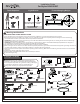
A. Pass the cable through one hole on the Fastener first and then turn back to pass the cable through another hole on the Fastener. Make a
small loop that is just large enough for the Screw. Once the loop size is determined, thread the Set Screw into the Fastener and hand
tighten until snug.
B. Place the Spring Washer and the Flat Washer onto the Screw and pass the Screw through the Cable loop. Thread the Screw into the
ceiling, structural support close to the Hanger Frame. Hand tighten until snug to secure the cable.
Note: If you would like to install the cable to concrete ceiling, Wall Anchors will be required. Using a 5/16-inch drill bit (not included), drill
pilot holes at marked locations.
STEP 3-SAFETY CABLE
2020 Quoizel Inc.
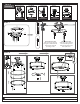
STEP 4
Making the wire connections using the receiver, for use with the remote control
A. Making the Wire Connections
1. Connect fixture wires with label “Light L” together;
2. Connect fixture wires with label “N” together;
3. Connect fixture wires with label “ Motor L” togther.
B. Making the Wire Connections
1. Wrap bare or green ground wire around green ground screw on the crossbar, no less than 2 inches from the end of the wire. Tighten the
green ground screw.
2. Use standard wire connectors (not included) to make all wire
connections. Twist connectors until wires are tightly joined together. Wrap each connection with approved electrical tape and carefully stuff
all the connected wires into outlet box.
Note: If the electrical wire is going to be cut shorter than provided you will need to identify the "L" line wire and the "N" neutral wire before
you cut the excess wire off. One is labeled N and the other labeled L. To do this separate the "L" line wire and the "N" neutral wire as far
as you need to. Re-label the wire near where you want to make the cut. Be sure to mark the wire on the side of the fixture and not on the
excess wire being cut and removed.
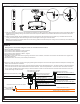
Blue wire from fixture
identified with the Label “LIGHT L”
White wire from fixture
identified with the Label “N”
Black wire from fixture
identified with the Label “MOTOR L”
AC L
AC N
White wire from outlet box
Black wire from outlet box (or Red)
Ground wire from Fixture
Bare, or Green
Ground wire
from outlet box
Green Ground Screw on the Crossbar
Ground wire from Hanger Frame
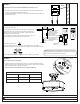
ON
ON DIP
1 2 3 4
Black Wire from controller
with the Label “MOTOR L”
White Wire from controller
with the Label “N”
White Wire from current-limiting
with the Label “N”
Black Wire from current-limiting
with the Label “LIGHT L”
Blue Wire from controller
with the Label “LIGHT
L”
Red Wire