
Instructions / Assembly


4 of 5
visit us on-line at www.quoizel.com
Making the wire connections without the received, the fan and light will be controlled by wall switches only.
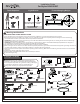
a. Making the Wire Connections,
1. Remove the current-limiting from the receiver.
2. Wrap bare or green ground wire around green ground screw on the crossbar, no less than 2 inches from the end of the wire. Tighten the green
ground screw.
3. Use standard wire connectors (not included) to make all wire connections. Twist connectors until wires are tightly joined together. Wrap each
connection with approved electrical tape and carefully stuff all the connected wires into outlet box.
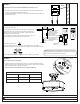
Note: If the electrical wire is going to be cut shorter than provided you will need to identify the "L" line wire and the "N" neutral wire before
you cut the excess wire off. One is labeled N and the other labeled L. To do this separate the "L" line wire and the "N" neutral wire as far as
you need to. Re-label the wire near where you want to make the cut. Be sure to mark the wire on the side of the fixture and not on the excess
wire being cut and removed.
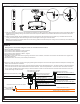
White wire
from outlet box
Black wire from
outlet box (or Red)
Ground wire from Fixture
Bare, or Green
Ground wire
from outlet box
Green Ground Screw on the Crossbar
Ground wire from Hanger Frame
Red wire from
current-limiting
Current-limiting
Black Wire from current-limiting
with the Label “LIGHT L”
White Wire from current-limiting with the Label “N”
Blue wire from fixture
identified with the
Label “LIGHT L”
Black wire from fixture identified with the Label “MOTOR L”
White wire from fixture identified with the Label “N”
Warning: If you would like to use wall switch to control the light
and fan, please refer to the switch installation instructions.
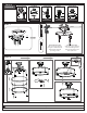
STEP 5
A. Insert the LED bulbs into the socket
and thread in place.
NOTE: This product is equipped with a
maximum 70W current limiter. The total
lamp wattage cannot exceed 70W or the
lamp will not light.
2020 Quoizel Inc.