
Installation Sheet

1of2
Thank you for purchasing a Quoizel product.
Need assistance with parts or assembly? Call Quoizel customer service at 1-631-273-2700
or visit us on-line at www.quoizel.com
2015 QuoizelInc.
Package Contents
A
Fixture
Body
x1
Pleasegoto forproduct cleaningtips. Goto the selection.www.quoizel.com Care+ Maintenance
ToolsRequired: Flatheadscrewdriver,Phillipsscrewdriver,pliers,wire cutters,wire strippers,electrical tape,safety glasses.
LightSource: (4)Medium Base100W Maximum,Alternatebulb(4) 23WCFL
EstimatedAssemblyTime:
Preparation:
30-45minutes
Identifyand inspectall partsbefore beginninginstallation. Checkpackage contentlist anddiagrams belowto besure allparts are
present.If anyparts aremissing ordamaged, donot attemptto assemble,install, oroperate thefixture. Contactcustomer servicefor replacement
parts.
Warnings and Cautions
Assembly Instruction Sheet #IS-GF1721
For Styles GF1721AN, GF1721PN, and WSGF1721C GF1721
Turn off electricity at circuit breaker or main fuse box before installation. Consult a licensed electrician if in doubt.
These instructions are provided for your safety. It is very important you read them completely before installing the fixture. We strongly
recommend that a licensed, professional electrician perform the installation.
Disconnect fixture from power source before replacing bulbs. Make sure bulbs are given sufficient time to cool before removal. Do not subject
glass parts to any shock while in operation or shattering may result.
February2015
D
Check
Ring
x2
E
Center
Stem
x1
F
Big Rubber
Washer
x1
G
Big Flat
Washer
x1
B
Ring
x1
C
Knob
x3
H
Spacer
Tube
x1
Shade
x1
K
Hex Nut
x1
L
Cap
x1
M
Finial
x1
N
Hardware Contents
AA
Crossbar Assembly
x1
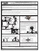
STEP 1 Attach Ring to Socket Assembly-
A. Unfold Side Arms at 120 degree locations as shown.
B. Place the Holes on the Ring (B) over the Bolts on the ends of the
Side Arms. Secure by threading Knobs (C) onto the Bolts. Hand
tighten until snug.
Figure 1
A
B
C
Bolt
Side Arm
STEP 2 Install Crossbar Assembly-
.
A. Pass the supply wires through the Crossbar Assembly (AA). Attach
the Crossbar Assembly (AA) to the Outlet Box with the head of the
Green Ground Screw facing you. Secure it with Outlet Box Screws
(not included). Tighten until snug
Figure 2
Supply Wires with
Ground Wire
AA
Outlet Box Screws
(not included)
Outlet Box
STEP 3 Fit Ceiling Canopy to Crossbar Assembly-
A. Remove mounting balls from the Crossbar Assembly (AA). Fit the
ceiling canopy of the Fixture Body (A) to the Crossbar Assembly
(AA) and secure with mounting balls. Note: The Ceiling Canopy
should be snug against the ceiling and the mounting balls. If not,
adjust the length of the nipple on the Crossbar Assembly (AA) by
unscrewing the preassembled hex nut and lock washer and then
screwing the mounting
screws in or out of the
crossbar until the correct
length is achieved. Once
the Ceiling Canopy is
secure, remove the
mounting ball and Ceiling
Canopy and proceed to
Step 4.
Ceiling
Canopy
AA
Hex Nut and
Lock Washer
Mounting
Screw
A
Mounting
Ball
Figure 3
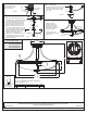
STEP 4 - Wire Connections
A. Use standard wire connectors (not included) to make all wire
connections. (Connectors are not included with fixture.) Twist
connectors until wires are tightly joined together. Wrap each
connection with approved electrical tape and carefully stuff all the
connected wires into the Outlet Box.
White wire
from supply
White wire
from fixture
Black wire from
supply (or Red)
Black wire
from fixture
Ground wire
from supply
Ground wire
from fixture
Figure 4
STEP 5 Install Fixture Body-
A. Carefully tuck all wires into the outlet box and position the Ceiling
Canopy on the Fixture Body (A) over the outlet box. Align the holes
in the Ceiling Canopy with the mounting screws, then attach the
I
Small Flat
Washer
x1
J
Small
Rubber
Washer
x1