
Installation Sheet

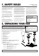

1. Disconnect the power by removing fuses or turning off circuit breakers.
2. If there is an existing outlet box, ensure it is clearly marked "Suitable for Fan
Support of 50 lbs (22.7 kg) or lesse". If it is not so marked, it must be replaced with an
approved one.
WARNING: Most outlet boxs commonly used for support of lighting fixtures are not
acceptable for fan support, and may need to be replaced. Due to the complexity of the
installation of this fan, a qualified licensed electrician is strongly recommened.
3. Secure the outlet box (or make sure the existing box is secured) directly to the
building structure. Use appropriate fasteners and building materials.
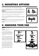
4. Figures 1 and 2 are examples of different ways to mount the outlet box in different
situations. A longer downrod may be required in sloped ceiling situations to maintain
proper blade clearance.
3. MOUNTING OPTIONS
WARNING: TO REDUCE THE RISK OF ELECTRIC SHOCK, FIRE, OR PERSONAL INJURY,
MOUNT THE FAN ONLY TO AN OUTLET MARKED ACCEPTABLE FOR FAN SUPPORT OF 50 LBS
(22.7 KG) OR LESS AND USE MOUNTING SCREWS PROVIDED WITH THE OUTLET BOX.
CAUTION: DO NOT MOUNT THIS FAN ON SLOPE CEILING.
Fig. 1
Ceiling Joists
Outlet Boxes
Fig. 2
Ceiling Joists
Outlet Boxes
WARNING -Turn off the power!
CAUTION: ALL PARTS ASSEMBLY SHOULD
BE WORKED AT THE FLOOR.
1. If not already affixed to the hanger
bracket, place the rectangular rubber isolators
between the hanger bracket and outlet box.
Secure the hanger bracket to the outlet box
using the 2 long steel screws supplied with
the outlex box.
2. Remove the set pin and safety lock clip
from the yoke on top of the motor assembly.
Slide the downrod through the canopy and
canopy cover. Slide the yoke cover onto the
downrod (Fig. 3). Feed the wires from the fan
motor through the downrod assembly.
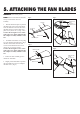
3. (Fig. 4) Attach the downrod assembly
(downrod, yoke cover, canopy and canopy
cover) to the motor by sliding the downrod
into the yoke on top of the motor assembly.
Slide the set pin through the hole in the yoke,
downrod and secure it with the safety lock
clip. Tighten the set screws on yoke. The
yoke cover will lower down to conceal the
yoke. Feed the wires through the downrod
ball.
4. HANGING YOUR FAN
Fig. 3
Downrod
assembly
Ceiling
canopy
Canopy
cover
Yoke cover
Fig. 4
Downrod
Set screw
Yoke
Safety
lock clip
Set pin
Canopy
Canopy cover
Yoke cover