
Installation Sheet

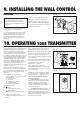

9. INSTALLING THE WALL CONTROL
Your DC brushless motor is equipped with an
automatically learned type remote control.
There are no frequency switches on the
receiver; the receiver unit will automatically
scan the frequency from the wall control if
any changes are made. The frequency settings
on the transmitter should be changed only in
case of interference or if a second or more
ceiling fans with the same type of control
system are installed in the same structure.
(Fig. 19) (It is recommended that you not use
the factory code settings. Change codes
setting to any other combination of dip switch
setting to avoid issues).
Remove the panel from the transmitter and
then install one 23A/12V battery (included).
To prevent damage to transmitter, remove the
battery if not use for long periods of time
(Fig. 19).
A. I, II, III, IV, V and VI buttons:
These six buttons are used to set the fan
speed as follows:
I = minimum speed
II = low speed
III = medium low speed
IV = medium speed
V = medium high speed
VI = high speed
B. button:
This button turns the fan off.
C. Reverse button:
This button is to control fan direction.
D. "SET" code setting button:
Follow the below steps to use the set
button.
Step 1. With the fan’s power off, arrange
code switches to desired code setting.
Step 2. After installing the unit and restoring
power to the fan, press and hold the “SET”
button 1 - 5 seconds. You must press the
“SET” button within 60 seconds of restoring
power to the fan.
Step 3. The fan will start to run and begin
the control setting process. The fan will run
in both directions for a total of
approximately 5 minutes.
Step 4. When the fan stops after
approximately 5 minutes, the control and
speed setting process is complete and the
fan is ready for use.
NOTE: If you want to change the blades: 1.
Turn off the power. 2. change the blades. 3.
turn the power on. 4. replay the step 2,3,4.
The receiver provides the following
protective function:
1. Lock position: The DC motor has a
built-in safety against obstruction during
operation. The motor will be locked
operation and disconnect power after 30
seconds of interruption. Please remove
obstacles before re-set.
2. Over 80W protection: When the
receiver detects motor power consumption
which is greater than 80W, the receiver
power will be stopped and operation will
immediately discontinue. Turn the receiver
power on after 5 seconds.
10. OPERATING YOUR TRANSMITTER
REMEMBER -Turn off the power!
1. Remove the existing wall plate and
switch from the wall junction box.
2. If your outlet box has a ground wire
(green or bare copper) connect the wall
control's ground wire to it; otherwise
connect the wall control's ground wire
directly to one of the screws from the
outlet box.
3. (Fig. 18) Carefully tuck the wire
connections inside the junction box.
Secure the wall control with the two
screws provided. Attach the wall plate
over the wall control and secure with the
two screws provided.
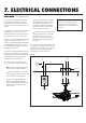
Hook up in "series only" do not connect
the hot and neutral wires of electric
circuit to the transmitter wall switch -
damage to the switch and possible fire
could occur.
Fig. 18
Fig. 19
Fig. 20